
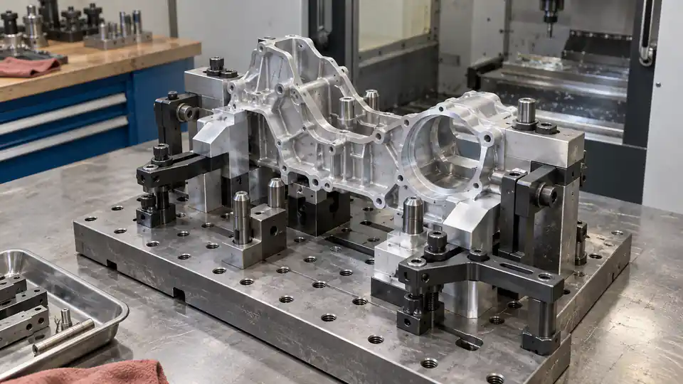
Every CNC part must be located, supported, and restrained while cutting forces act on it. Standard vises, collets, chucks, and modular clamps cover many jobs. Custom workholding becomes necessary when the geometry is irregular, the walls are flexible, several parts must run together, a datum must be transferred accurately, or production volume justifies faster loading.
This custom tooling fixture CNC cost guide explains what suppliers include, why fixture cost is not simply divided by quantity, and how buyers can protect repeatability without prescribing the shop’s proprietary method. The central question is whether the proposed fixture creates the part’s functional datums reliably while leaving enough access to machine and inspect it.
What Counts as Custom Workholding
Custom workholding includes soft jaws machined for one part, dedicated fixture plates, nests, expanding mandrels, hydraulic or pneumatic fixtures, vacuum plates, adhesive carriers, tombstones, pallet systems, sacrificial frames, and purpose-built inspection fixtures. It can also include modified standard components and part-specific locating pins.
Some tooling is consumable; some lasts for a program; some is re-machined after every revision. The quote should identify what is being supplied rather than using one unexplained “tooling” line.
Separate Workholding from Cutting Tools
End mills, drills, reamers, inserts, taps, form cutters, broaches, and grinding wheels create features. Fixtures and jaws position the work. A special form tool and a custom nest may both be required, but their life, ownership, replacement, and amortization differ.
Ask suppliers to separate fixture engineering, fixture hardware, special cutting tools, inspection gages, and consumable tooling. This makes quantity breaks and repeat-order prices understandable.
The Fixture Must Establish the Datum Reference
A robust fixture locates the part from surfaces or features that correspond to the drawing’s functional datum strategy. If the shop locates from a rough edge while the drawing controls features from a finished bore, datum transfer and stock variation can consume tolerance.
The supplier may create temporary process datums during early operations, then relocate from finished datums later. That is acceptable when the route controls the relationship. Request a setup sketch or datum narrative for critical work; do not demand proprietary dimensions that are unnecessary to approve the concept.
The 3-2-1 Principle
For a rigid prismatic part, a common locating concept uses three contacts to establish a primary plane, two contacts for a secondary direction, and one contact for the tertiary direction. Clamps seat the work against those locators without adding an unintended degree of constraint.
Real parts complicate the model. Cast or saw-cut surfaces are imperfect, flexible plates deform, and pins in holes may create redundant constraints. Use the principle to reason about degrees of freedom, then adapt contact size, relief, and sequence to the geometry.
Avoid Overconstraint
Too many rigid locators can make the part rock, prevent seating, or force it into a distorted condition. Two round pins in two close-tolerance holes can bind if hole spacing varies. A round pin plus a relieved diamond pin is a common way to locate while accommodating spacing variation.
Overconstraint also makes results sensitive to chips or burrs. Identify the minimum contacts that fully locate the part and provide clearance elsewhere. For flexible components, use supports that stabilize cutting without redefining the finished free-state geometry.
Clamp Force Must Oppose Cutting Without Distortion
Clamps should push the part toward locators and resist expected forces and moments. A clamp far from a support can bend a thin wall or plate. Excess force can make the part appear flat during machining and spring out of tolerance after release.
The workholding plan should define clamp positions, sequence, pressure or torque where important, and support under high-load regions. Hydraulic systems need pressure control; manual clamps need repeatable operator practice.
Tool Access Shapes the Fixture
Locators and clamps cannot block the cutter, holder, probe, coolant, chip flow, or machine travel. A fixture that is mechanically strong but shadows a feature can force extra setups or long-reach tools. Five-axis fixtures often minimize obstruction and hold from a compact sacrificial region.
Review access with the complete tool assembly at extreme positions. Include deburring and inspection access, not just roughing.
Soft Jaws
Soft jaws are standard chuck or vise jaws machined to fit a part profile. They are fast to produce, relatively inexpensive, and useful for second operations on turned or milled components. Correctly bored jaws can support a finished diameter while controlling runout and clamp marks.
Their usable life depends on material, clamping, recuts, wear, and storage. Record jaw set, machine, chuck or vise, boring condition, part orientation, and revision. A jaw made for one machine may not reproduce its result on another.
Dedicated Fixture Plates
A fixture plate combines locators, clamps, supports, and sometimes multiple part stations. It can improve repeatability and allow probing or automated loading. The plate may mount directly to a table, pallet, rotary, tombstone, or zero-point system.
Dedicated plates require design, programming, manufacture, assembly, and qualification. Modular bases can reduce these costs, but the part-specific top tooling remains controlled.
Collets and Expanding Mandrels
Collets grip round external surfaces over broad contact and can support fast, concentric loading. Expanding mandrels locate or clamp from a bore, leaving the outside accessible. Both depend on size range, form, surface condition, length, and clamp force.
If the bore is a functional datum, an expanding mandrel may align the process well. If the bore is thin or unfinished, expansion can distort it. State whether gripping marks or temporary deformation are acceptable.
Vacuum Workholding
Vacuum fixtures suit plates and sheets with enough sealing area. They give broad support and clear top access but limited resistance to lateral force. Porosity, through-holes, roughness, leaks, coolant, gasket condition, and available vacuum determine holding force.
The route may leave tabs, use low-force toolpaths, or cut through only in a final step. Vacuum loss detection and a safe stop matter for unattended cutting.
Adhesive, Wax, and Carrier Methods
Thin, small, or delicate parts can be bonded to a carrier with adhesive, tape, wax, solder, or a temporary compound. The method spreads support and avoids mechanical clamp marks. It adds surface preparation, cure, removal, cleaning, temperature, and contamination controls.
Validate compatibility with part material, finish, vacuum service, medical cleanliness, or later coating. Include carrier flatness and bond-line variation in the process plan.
Sacrificial Tabs and Frames
A part can remain attached to extra stock by tabs or a surrounding frame during most operations. The frame provides stiffness and clamping, then is cut away. This is common for thin profiles and five-axis parts held by a dovetail or base.
Tab removal introduces a final cut, blend, deburr, and possible distortion. Mark permitted tab regions and cosmetic limits. Include the sacrificial volume in material and cycle estimates.
Modular Versus Dedicated Fixtures
Modular clamps and locators reduce design and fabrication time for prototypes and changing work. They may take longer to load, occupy more access space, and rely more on setup skill. Dedicated fixtures cost more initially but can reduce cycle, improve poka-yoke, and support repeat volume.
| Factor | Modular setup | Dedicated fixture |
|---|---|---|
| Upfront cost | Lower | Higher |
| Lead time | Shorter | Design and build required |
| Loading speed | Often slower | Can be optimized |
| Revision flexibility | High | Depends on design margin |
| Repeatability | Operator/setup dependent | Designed and qualified for the part |
| Automation | Limited or adaptable | Can integrate sensing and actuation |
Quantity, release cadence, tolerance, operator skill, and revision risk determine the better choice.
One-Part Versus Multi-Part Fixtures
A multi-part fixture spreads tool changes and probing across several components and improves machine utilization. It also increases fixture size, chip accumulation, loading time, and risk: one programming or locating error can affect multiple blanks.
Analyze how stations share datums and whether errors vary across the machine table or rotary. Qualify each station and preserve station identity in inspection data when necessary.
Hydraulic and Pneumatic Clamping
Powered clamping provides consistent force and fast actuation. It can sequence supports and clamps, integrate pressure switches, and support automation. It adds pumps, valves, hoses, seals, maintenance, leak risk, and safety controls.
The fixture should fail safely during pressure loss and detect incomplete clamp states before spindle start. Define pressure ranges and periodic verification rather than assuming automation equals repeatability.
Tombstones, Pallets, and Zero-Point Systems
Tombstones hold parts on multiple vertical faces, often in horizontal machining centers. Pallets and zero-point interfaces allow fixtures to be prepared offline and exchanged repeatably. These systems can reduce idle setup time and support flexible production.
Their accuracy depends on clean, maintained interfaces and known repeatability. The quote may include a part-specific fixture mounted to shop-owned base hardware. Ownership language should distinguish them.
Fixture Material and Stability
Steel provides stiffness and wear resistance; aluminum reduces weight and machining time; cast iron offers damping and stability; engineering plastics or printed components can serve light-duty nests. Hardened inserts may protect locator and clamp contacts.
Consider coolant compatibility, corrosion, thermal expansion, abrasion, and repair. A large aluminum fixture and steel part can shift relative location with temperature. Precision tools may need stabilization and recalibration.
Locators and Wear
Pins, buttons, pads, cones, nests, and mandrels wear or collect damage. Replaceable hardened components can preserve the fixture body. Critical locators need inspection intervals and defined replacement limits.
Fixture qualification should measure the interfaces that determine part position, not only the overall plate. Maintain a tool ID and history so worn tooling is not returned to service without review.
Error-Proof Loading
Asymmetric locators, keying, sensors, part-present switches, barcode checks, and clear work instructions reduce wrong orientation or revision mixing. A fixture that accepts the part backward can create scrap before inspection detects it.
Error-proofing is especially valuable for families with similar blanks. It can add nonrecurring design cost while reducing recurring risk and operator attention.
Chip and Coolant Management
Locating surfaces must remain clean. Pockets that trap chips can lift a part, mark a finished surface, or prevent a clamp from seating. Relief channels, air blast, coolant flow, sloped surfaces, access for cleaning, and positive seating detection help.
Define cleaning frequency and verify that an air blast does not create a safety or contamination problem. In automated cells, chip accumulation should be tested over realistic run length.
Fixture Qualification
Qualification confirms that the assembled tool, on its intended machine, creates the required location and does not distort the work. Methods can include CMM inspection of locators, master artifacts, probe qualification, test cuts, capability studies, or correlation with inspection fixtures.
Record fixture revision, machine interface, locator values, clamp settings, measurement method, acceptance limits, and date. Requalify after repair, collision, locator replacement, design change, or transfer to a different base system.
Verify Safe Load and Failure Behavior
The fixture must retain the work through the most adverse credible cutting load, spindle acceleration, indexing move, and loss of a powered service. Engineering should consider clamp capacity, friction assumptions, locator shear, fastener strength, hydraulic pressure, vacuum area, center of mass, and imbalance. Apply the machine builder’s and workholding manufacturer’s limits rather than an informal shop estimate.
Powered fixtures need interlocks or status confirmation appropriate to the risk. A pressure switch can show line pressure but may not prove that every clamp contacted the part. Sensors, seating checks, programmed probe moves, or a controlled load sequence can provide additional evidence. Establish what the machine does after pressure or vacuum falls: stop safely, preserve tool clearance, and prevent an automatic restart with an uncertain part position.
Document lifting and installation for heavy fixtures. Provide rated lifting points, center-of-gravity information, transport restraints, and storage supports. Machine guarding and safe access remain part of the production method even when the fixture is customer-owned.
Design for Reuse Without Losing Control
A family fixture can share a base, pallets, clamps, and control connections while using replaceable nests or locator modules. This can reduce later tooling cost and lead time. It also creates configuration risk if the wrong insert, program, or pressure setting is selected.
Assign every module a part-family and revision identifier. Use keyed interfaces, presence detection, or a setup checklist where mix-ups are credible. Qualify the complete configuration, not just the reusable base. When the family grows beyond the original envelope, repeat collision, load, chip, and accuracy reviews instead of assuming modularity guarantees compatibility.
In the quote, separate durable common hardware from part-specific inserts. That distinction supports fair amortization, spares planning, and transfer while showing which savings are available to future components.
Inspection Fixtures Are a Separate Decision
A manufacturing fixture is designed to resist cutting forces; an inspection fixture establishes a repeatable measurement state without excessive distortion. Reusing one for the other may be valid, but it is not automatic. Coolant residue, wear, thermal state, and access can affect results.
If the drawing defines restraint or datum simulators, the inspection tool must reproduce them. List inspection-fixture cost and qualification separately from machine workholding.
Nonrecurring Engineering and Build Cost
Fixture cost can include concept review, CAD, analysis, purchased components, fixture material, machining, assembly, plumbing or wiring, programming, tryout, qualification, documentation, and project management. Rush work and scarce components add cost.
Request a breakdown detailed enough to understand the scope, not the supplier’s confidential labor rates. Confirm whether design changes after approval are included.
Recurring Fixture Cost
Recurring cost includes loading labor, cleaning, periodic verification, wear items, hydraulic seals, sacrificial components, and time to install or remove the fixture. A dedicated tool that reduces cycle by two minutes may pay back quickly at volume but not on a five-piece prototype.
Include expected life and replacement policy. A quote that amortizes one fixture across 1,000 parts should say what happens if the order stops at 100 or grows to 5,000.
Amortization and Quantity Breaks
If a fixture costs $4,000 and saves $8 per part versus a modular setup, simple break-even is 500 parts before financing, maintenance, storage, and risk. The buyer may pay tooling upfront, amortize it into units, or let the supplier own it as part of price.
Each model has commercial consequences. Upfront payment does not automatically establish legal ownership, and ownership does not guarantee that the tool can run elsewhere without the supplier’s base hardware, programs, or know-how.
Ownership, Storage, and Transfer
Purchase terms should identify owner, marking, possession, maintenance, insurance, storage period, access, permitted use, and disposition. Customer-owned tooling should be physically identified and protected from use on unrelated work.
For transfer, define what will be supplied: fixture assembly, CAD, drawings, bill of materials, programs, qualification data, master parts, and special setting tools. Proprietary shop-standard bases may remain excluded. Resolve this before award.
Revision Risk
A small part revision can invalidate a dedicated nest, move a clamp, change stock, or alter datum strategy. Build adjustment range and replaceable inserts into the design when likely changes are known. Do not freeze a flexible prototype around an expensive production tool too early.
Record the part revision qualified on each fixture. A change review should assess fit, access, force, chips, inspection, and error-proofing—not just whether the new CAD opens in the CAM system.
Lead-Time Risks
Custom cylinders, clamps, cast bases, zero-point components, sensors, and special steels may have long procurement. Fixture design usually begins only after stable models and critical requirements are available. First-article debugging can add calendar time.
Ask for a tooling schedule with design approval, component order, build, prove-out, qualification, and first-article milestones. Parallel work can shorten lead time but increases risk if the design changes.
Cost Comparison Table
| Quote element | One-time, per batch, or recurring? | Evidence to request |
|---|---|---|
| Fixture design | One-time | Concept, revision, approval point |
| Fixture build | One-time/replacement | BOM scope and delivered hardware |
| Special cutter | Consumable or one-time lot | Tool ID, expected life, ownership |
| Setup and alignment | Per batch | Hours and number of operations |
| Load/unload | Per part or pallet | Standard cycle assumption |
| Qualification | Initial and after defined events | Report and acceptance limits |
| Maintenance/wear | Periodic | Interval and replacement policy |
| Storage | Annual or included | Location and retention period |
Use the table to compare equivalent scope across suppliers.
What the Buyer Should Provide
Send the 3D model, controlled drawing, material and stock condition, quantities and release cadence, critical datums, tolerances, cosmetic surfaces, allowed clamp regions, inspection evidence, and automation assumptions. Identify features expected to change during development.
Do not dictate jaw brands or fixture architecture unless interface or validation requirements make it necessary. Ask the supplier to propose the simplest controlled method and identify any drawing change that reduces fixture complexity.
Questions Before Award
- Which surfaces or features locate each operation?
- How are all six degrees of freedom controlled without overconstraint?
- Where do clamps and supports act, and how is distortion limited?
- What tool and probe access has been collision-checked?
- Which components are custom, consumable, or shop-standard?
- How is the fixture qualified and requalified?
- What loading, cleaning, and seating checks are required?
- How does tooling cost change across quantities and releases?
- Who owns, stores, maintains, and may use the tooling?
- What files and hardware transfer if production moves?
- Which part revisions or geometry changes invalidate the tool?
- What backup route exists if the fixture is damaged?
Release Checklist
- Tie locators to functional or controlled process datums.
- Control six degrees of freedom without redundant rigid contacts.
- Direct clamps toward supports and limit part deformation.
- Check cutter, holder, probe, coolant, chip, and deburring access.
- Qualify every station and powered-clamp state.
- Identify fixture, cutters, gages, and consumables separately.
- State nonrecurring, per-batch, and per-part charges.
- Record tool ownership, storage, maintenance, and transfer rights.
- Define fixture life, wear limits, spares, and requalification triggers.
- Keep part and fixture revisions linked.
- Include error-proofing for orientation and part-family mix.
- Approve the concept before irreversible tooling spend.
The Practical Quoting Decision
Custom workholding is valuable when it creates repeatable datums, supports the part without distortion, opens tool access, and reduces setup or handling enough to justify its lifecycle cost. It is wasteful when it locks an unstable design into expensive hardware or hides a poor datum strategy.
Compare the entire route: tooling engineering, build, qualification, cycle savings, maintenance, revision risk, ownership, and transfer. To obtain a fixture-aware process review, send the 3D model, controlled drawing, quantities, release plan, and acceptance requirements through Request a Quote.