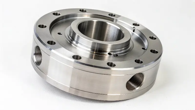
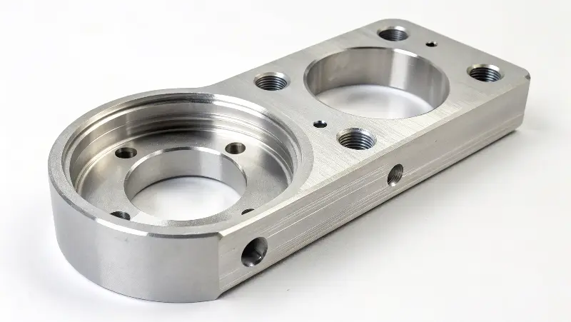
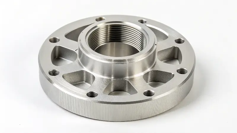
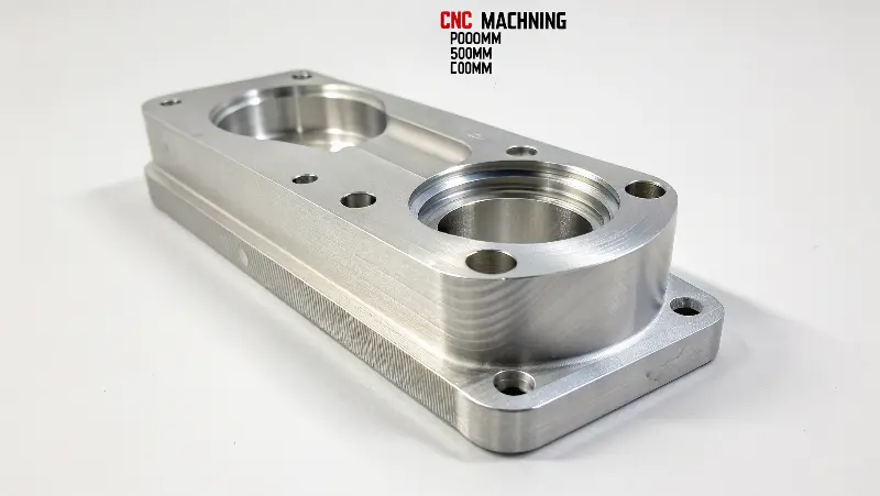
This large H13 tool-steel example helps mold and tooling buyers review the decisions behind machining an 800 × 500 × 250 mm component. The recorded route includes 3-axis / 4-axis CNC milling, polishing, one-piece supply and a project-specific ±0.01 mm tolerance.
H13 stock condition, heat-treatment stage, machining allowance and final polishing requirement must be confirmed before the process route is released. For a component of this size, the RFQ should also identify functional datums, access restrictions and whether critical dimensions apply before or after any thermal or finishing operation.
Large Tool-Steel Stock and Stress Control
Rough machining removes substantial material and can expose residual stress. Stock allowance, balanced roughing and suitable stabilization checks should be planned around the supplied H13 condition rather than assuming one standard route for every tool-steel component.
Datum Transfer and Polishing Allowance
Large faces, bores and tooling features may require more than one setup. Stable references should be carried between operations, while the polishing allowance is reserved only where the drawing requires it so functional edges and dimensions are not changed unintentionally.
Final-Condition Requirements
The drawing should state material condition, heat-treatment responsibility, final surface state and the features linked to the ±0.01 mm requirement. These inputs determine when finishing and inspection should occur.
Process Plan
Drawing Review → H13 Condition Confirmation → Datum and Setup Planning → Balanced Roughing → Finish Machining and Polishing → Final-Condition Inspection
Grinding, EDM, heat treatment or hardness testing are included only when the current drawing and quotation require them.
Inspection Approach
CMM, height gauge, micrometer or bore gauge may be used according to feature size, datum accessibility and tolerance type. Surface roughness measurement and hardness testing are defined during drawing review when the finish or H13 condition makes them relevant; no specific device is implied without an agreed inspection plan.
What This Example Demonstrates
This example helps customers identify the stock condition, datum scheme, polishing allowance and final inspection condition that should be resolved during an RFQ for large mold and tooling components.
Send the current STEP or IGES model, controlled drawing, H13 condition, quantity, critical features and polishing requirement for an engineering review.