
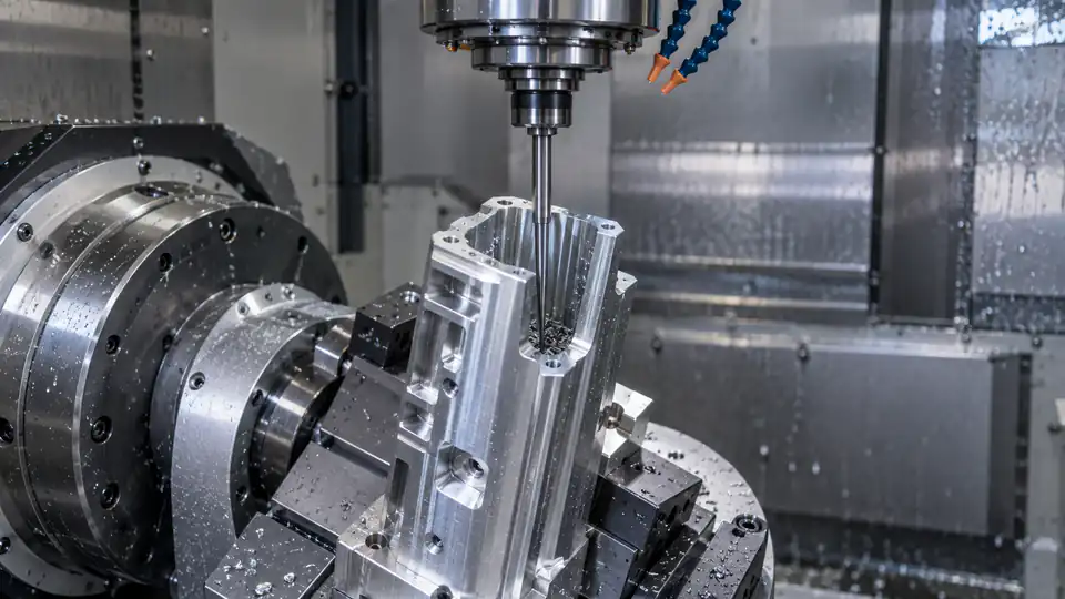
A cutter that can touch a feature in CAD may still be unable to machine it productively. Deep pockets, tall walls, overhangs, narrow openings, and recessed side features force the cutting edge farther from the spindle or holder. That extra reach reduces stiffness, increases deflection and chatter risk, obstructs coolant and chips, and can turn a short operation into many conservative passes.
This long reach tool CNC cost guide explains the geometry, toolholding, process, quality, and design trade-offs behind the quote. The goal is to distinguish unavoidable functional depth from access restrictions that can be removed before release.
Reach, Stickout, and Aspect Ratio
Reach is the distance from the holder or spindle obstruction to the cutting region. Tool stickout is the unsupported length from the holder to the active cutter. They are related but not identical: a long-neck end mill may reach past a wall while keeping only part of its diameter relieved, and a compact holder may reduce required stickout.
A useful screening ratio is unsupported length divided by cutter diameter, L/D. As L/D grows, bending stiffness falls sharply. For a simple beam-like tool, deflection is proportional to load and roughly to length cubed, and inversely proportional to elastic modulus and section moment. Doubling unsupported length can therefore produce far more than double the deflection.
Why Small Diameter Makes Reach Harder
The area moment of inertia of a round section rises with diameter to the fourth power. A modest reduction in cutter or neck diameter can cause a large stiffness loss. Narrow slots and small internal corner radii often force exactly that reduction.
This interaction explains why a deep cavity with generous floor area can still be expensive: if its entry opening or corner radius limits the cutter, the supplier cannot use the stiffer tool that would otherwise remove material efficiently.
Holder Collision Defines the Real Access Envelope
CAM collision checking must include spindle nose, holder, collet or shrink-fit body, tool shank, neck, cutting flute, fixture, clamps, and stock. Checking only the cutter tip gives a false result. The holder may contact a wall before the tool reaches the floor, especially on draft-free cavities.
Ask for an access section showing the tool and holder at the deepest and most obstructed positions. For five-axis work, sweep the full orientation range and include rotary limits and machine structure.
Tool Deflection Changes Size and Form
Radial cutting force bends the tool away from the work. The top of a deep wall may be closer to nominal while the lower region has taper or stock left behind, depending on toolpath and engagement. On opposite walls, deflection can change slot width or boss size in different directions.
Spring passes may reduce error, but they add time and cannot fully correct unstable cutting. Finishing allowance, climb direction, entry, step-down, radial engagement, and compensation must be planned around the feature.
Chatter Is a System Response
Chatter is self-excited vibration involving tool, holder, spindle, workpiece, fixture, and cutting process. Long overhang lowers dynamic stiffness and can place the system in an unstable speed-engagement region. The result may be poor finish, dimensional variation, noise, tool damage, or spindle load spikes.
Reducing feed alone may not cure chatter and can worsen rubbing. Suppliers may adjust spindle speed, tooth count, helix, radial immersion, depth, toolpath, holder, or damping. A quote often includes conservative parameters until the stable window is proven.
Runout Becomes More Damaging
Holder, spindle, collet, shank, and assembly cleanliness contribute radial runout. At long reach, angular error at the holder produces larger displacement at the cutting edge. Unequal tooth loading can then accelerate wear or break a small tool.
Low-runout holders, clean interfaces, balanced assemblies, correct clamping length, and measured tool setup help. These controls add preparation and inspection time that may appear in the price.
Toolholder Choice Affects Access
Side-lock holders are robust but bulky and can introduce runout. ER collets are flexible but their nut diameter may restrict deep-wall access. Hydraulic and shrink-fit holders can offer slim profiles and good runout, with their own equipment, heat, maintenance, and pullout considerations. Milling chucks and power-shrink systems serve other rigidity needs.
No holder type is universally best. The chosen assembly must meet torque, balance, runout, gauge length, coolant, and collision requirements for the machine and cutter.
Extended-Reach and Reduced-Neck Tools
An extended-reach cutter may have long flutes, a long shank, or a relieved neck behind shorter flutes. A reduced-neck tool can reach beside a wall while keeping the cutting length only as long as needed, reducing rubbing and preserving some stiffness.
Catalog availability matters. An unusual diameter, corner radius, flute length, neck length, coating, or coolant feature may require a special tool with longer lead time and minimum purchase. Standardizing geometry around available tools can reduce both price and schedule risk.
Carbide, Steel, and Damped Tooling
Solid carbide has higher stiffness than steel and is common for long-reach end mills and boring bars, but it is brittle and costly at large diameter. Carbide-reinforced or heavy-metal bars, modular systems, and tuned or damped boring bars can extend stable reach.
Special tooling is justified when the feature is functionally necessary and volume supports it. The RFQ should identify whether the tool cost is nonrecurring, consumed per lot, or retained for repeat orders.
Milling Deep Pockets
Deep pockets combine long reach, wall collision, chip recutting, and coolant delivery. Rough with the shortest and largest tool that can access each level, leaving controlled stock. Step down only when surrounding geometry requires it, and use rest machining for areas left by larger tools.
Finishing may use a separate reduced-neck tool, light radial engagement, multiple depth bands, and a floor pass. Avoid forcing one long tool to perform all roughing and finishing.
Corner Radius Controls Cutter Diameter
An internal corner cannot be cut with a cylindrical end mill larger than the allowed radius. In practice, the cutter radius should be smaller than the design radius to permit toolpath motion and avoid full-width engagement in the corner. Deep sharp corners are therefore a compound penalty: small diameter plus long reach.
Increase vertical corner radii where function allows. Differentiate a floor fillet from a wall corner; each affects tool choice differently. A dog-bone relief or assembled insert may solve a square mating requirement.
Deep Slots and Narrow Channels
A narrow slot requires a small tool, and full-width slotting loads both sides of the cutter while limiting chip escape. At high depth, the tool may rub, pack chips, or deflect. Trochoidal paths, staged depth, air blast, through-tool coolant, and specialized cutters can help.
Widening the slot even slightly may permit a stiffer tool or lower engagement. If the slot carries fluid, wire, or a key, specify the functional clear width and corner condition rather than copying an arbitrary nominal.
Tall Thin Walls Add Workpiece Deflection
The tool is not the only flexible member. Tall thin walls bend under cutting force and may spring after unclamping. Removing supporting stock too early makes the final passes unstable. A supplier may rough both sides in balance, leave ribs or tabs, use low-force toolpaths, and finish in alternating steps.
Allowable wall taper, thickness, profile, and free-state inspection must be explicit. A tight tolerance over the full height can require specialized support or redesign.
Deep Bores and Boring Bars
Long boring bars face deflection, chatter, chip evacuation, coolant, and measurement access. Boring produces one cutting edge and can accurately finish diameter and location, but stable overhang depends on bar material, diameter, insert geometry, engagement, and machine condition.
Provide bore diameter, depth, bottom geometry, entry, interruption, texture, straightness, cylindricity, coaxiality or position, and final process state. A large entry chamfer or access from the opposite side may transform the route.
Deep Drilling
Depth-to-diameter ratio influences drill type and cycle. Peck drilling can clear chips but adds retract time and may mark the bore. Through-tool coolant, pilot drilling, gun drilling, or dedicated deep-hole equipment may be required for straightness and surface needs.
Blind-hole point depth and chip space matter. The drawing should distinguish full-diameter depth from drill-tip depth and leave relief for chips or coolant where possible.
Undercuts and Recessed Side Features
T-slots, internal grooves, backside counterbores, and radial ports may require lollipop cutters, slotting cutters, angle heads, right-angle tools, EDM, or an additional setup. Access must cover both insertion and cutting motion.
Model the entire relief, not just the final visible surface. State which corners may retain tool-radius transitions. If an assembled two-piece design can replace an inaccessible monolith, compare sealing, alignment, fasteners, and qualification before changing it.
Three-Axis Versus Five-Axis Access
Three-axis machining approaches along fixed setup directions. Five-axis positioning can tilt the tool to avoid a wall, shorten effective stickout, and machine several faces without reclamping. Simultaneous motion can follow complex surfaces with a better tool orientation.
Five-axis is not a magic solution. Holder collision, rotary travel, singularities, machine accuracy, tool-center-point control, verification, and higher machine rate remain. The supplier should show which setup or reach problem it eliminates.
Split the Feature Across Setups
Machining a deep feature from both ends can reduce reach if the geometry permits a blend, overlap, or controlled step. Opposed bores can be aligned by common datums and qualified process methods. A split route may introduce mismatch or an additional datum transfer.
Define whether the meeting line is functional and how it is inspected. For flow passages, surface steps can affect pressure loss or cleaning; for clearance cavities, a small blend may be irrelevant.
EDM as an Alternative
Sinker EDM can create deep ribs, small radii, and difficult access in conductive material, while wire EDM can produce through profiles when a wire path and start hole are possible. EDM trades cutting-force problems for electrode or wire access, burn time, recast layer, flushing, and electrode manufacture.
Use EDM where geometry and material justify it, not simply because milling looks difficult. State surface integrity, corner radius, overburn, heat-affected/recast requirements, and inspection.
Additive or Fabricated Alternatives
Additive manufacturing, brazed assemblies, welded fabrications, inserts, and bolted subassemblies can create internal access that machining cannot. They introduce material-property, distortion, cleanliness, leak, fatigue, and qualification questions.
For stable production, redesign may be worthwhile; for a prototype, specialized long-reach machining may be faster. Compare the complete validated route rather than only the machining operation.
Coolant and Chip Evacuation
Deep cavities trap hot chips. Recutting damages the tool and surface, while packed chips can break a cutter. Air blast, high-pressure coolant, through-tool delivery, minimum-quantity lubrication, evacuation pauses, and tool orientation help, subject to material and safety controls.
Plastic chips may soften or scratch; titanium chips retain heat; aluminum can weld to the edge. The process must match material and geometry. Enclosed pockets may require programmed retracts that add noncutting time.
Thermal Growth and Tool Length
Long cycles warm spindle, tool, fixture, and part. A long gauge length amplifies some geometric effects, and small tools can heat rapidly. Machine warmup, temperature compensation, probing, semi-finish stabilization, and controlled final passes may be needed.
The inspection state matters. A feature measured immediately on the machine can differ after the part equilibrates. Define final acceptance temperature according to the drawing and metrology practice.
Inspection Access Must Also Fit
A CMM stylus, bore gage, air gage, profilometer, optical sensor, or replica material must reach the controlled surface without an unstable extension. The manufacturing tool may fit while the inspection probe cannot. Long styli also bend and increase uncertainty.
Design and quality should review probe access with cutter access. If a functional gage or destructive section is needed, include it in the quote and acceptance plan.
Control Tool Pullout and Axial Movement
Helical cutting forces can pull an end mill from an inadequately clamped holder, changing depth and potentially driving the tool into a floor. The risk increases with aggressive engagement, long gauge length, poor shank contact, contamination, or an unsuitable collet. A holder that prevents pullout may be bulkier and therefore require additional wall clearance.
The process plan should specify the holder, shank condition, insertion depth, tightening method, torque where applicable, and inspection of witness marks or measured length. Tool-length probing can detect some movement, but a check made only after the part is complete may not prevent damage. Critical deep operations may need checks between toolpath stages.
Balance pullout protection against runout and access. Weldon flats, hydraulic systems, shrink fit, mechanical anti-pullout designs, and collets have different performance. Follow tool and holder manufacturers’ limits; do not improvise a reduced insertion length merely to gain reach.
Prove the Process at the Deepest Condition
A shallow test cut does not qualify the deepest operation. During first article, verify spindle load, vibration or sound, chip evacuation, tool wear, wall taper, floor depth, surface texture, and dimensional change after unclamping. Record the exact tool assembly and its measured gauge length.
If the CAM route divides the feature into depth bands, inspect transitions for steps or blends. For a long wall, sample geometry at several heights rather than measuring only the accessible top. For a blind bore, verify diameter, straightness, bottom condition, and debris removal to the required depth.
Release repeat production only after the observed stability supports the planned tool-life interval. Define when the cutter is replaced, what in-process signal prompts a stop, and how the last accepted part is identified after a failure. This evidence is more useful than an unsupported claim that the operation is within machine capability.
Retain the verified CNC program, tool list, holder assembly, preset data, fixture revision, inspection program, and approved parameter window as one process baseline. If production moves to another spindle, holder, machine model, or cutting-tool batch, repeat the checks affected by that change before assuming the original reach qualification still applies.
Record any approved temporary deviation separately; it must not silently become the default process for future lots or revised parts.
How Reach Affects Cost
Long reach adds cost through slower feed and engagement, more step-downs, separate rough and finish tools, rest machining, tool replacements, holders, probing, setup changes, scrap allowance, and longer inspection. It may also reserve a five-axis machine or EDM resource with a higher hourly rate.
| Reach driver | Cost mechanism | Evidence to request |
|---|---|---|
| Small cutter at high L/D | Reduced cutting load and shorter tool life | Proposed diameter, stickout, and operation |
| Holder-wall clearance | Slim or special holder; five-axis tilt | Collision/access section |
| Deep chip pocket | Retracts and coolant strategy | Toolpath and evacuation concept |
| Tight deep-wall profile | Semi-finish, compensation, spring passes | Finish plan and inspection method |
| Inaccessible measurement | Long stylus or dedicated gage | Inspection access plan |
| Nonstandard tool | Purchase and lead time | Tool identification and ownership |
Ask which feature creates each allowance. That makes DFM changes auditable.
Design Changes with the Highest Leverage
- Increase internal wall radii so a larger tool can enter and turn.
- Open the cavity or add access from another face.
- Reduce unnecessary depth or move a floor upward.
- Widen narrow slots and necks.
- Add draft or wall relief where parallelism is not functional.
- Separate floor and wall finish requirements.
- Limit tight profile to the active interface.
- Provide stable clamping and datum pads.
- Permit a blend where opposed operations meet.
- Split the component or use an insert after assembly review.
Evaluate strength, sealing, fatigue, cleanliness, appearance, and mating geometry before release.
A Quantitative DFM Comparison
Ask the supplier to compare the released geometry with one alternative. Record tool diameter, effective L/D, number of depth levels, estimated cycle, required holder, setups, special tools, inspection method, and predicted cost. A proposal such as “increase radius from 3 to 6 mm” becomes useful only when linked to the resulting tool and route.
Do not accept a broad percentage without assumptions. Quantity changes whether a special fixture or tool is worthwhile, and a cost improvement can disappear if a new inspection or assembly requirement is added.
What to Put in the RFQ
Send the 3D model and controlled 2D drawing, material and condition, stock restrictions, quantities, critical features, final surface requirements, tolerances, inspection evidence, and delivery. Identify mating regions so suppliers know which depths, radii, and surfaces may change.
Request a tool-access review before award for every deep or obstructed feature. The response should distinguish “machinable,” “machinable with special route,” and “not reliably verifiable,” and should list deviations requiring engineering approval.
Supplier Questions
- What cutter, holder, and gauge length are proposed at the deepest feature?
- What is the limiting L/D or collision condition?
- Which operations use reduced parameters because of reach?
- How will chips and coolant reach the cutting zone?
- How will deep-wall size, taper, profile, and finish be verified?
- Is five-axis positioning, EDM, or another setup required?
- Which tooling is special, and who owns it for repeats?
- What geometry change provides the largest cycle or risk reduction?
- What part state and temperature control final inspection?
- How will tool wear or chatter be detected before a nonconforming part is completed?
Release Checklist
- Check tool, holder, spindle, stock, and fixture collision together.
- Record cutter diameter, flute length, neck, stickout, and gauge length.
- Review L/D for milling, boring, drilling, and inspection probes.
- Provide larger radii and openings where function permits.
- Separate roughing, semi-finishing, and finishing strategies.
- Include chip evacuation, coolant, runout, and thermal controls.
- Assess workpiece deflection as well as tool deflection.
- Compare three-axis, five-axis, opposed setups, and EDM.
- Define deep-feature tolerance, texture, blend, and inspection state.
- Require a quantified DFM alternative, not a generic warning.
- Include special tools, cycle allowance, inspection, and risk in the quote.
- Approve any geometry change through revision control.
The Practical Design Decision
Long reach is a stiffness and access problem, not merely a tool-catalog selection. The price rises when small diameter, long unsupported length, obstructed holders, poor chip flow, flexible walls, and difficult measurement occur together. Improving even one of those conditions can unlock a faster and more reliable route.
Before release, ask the supplier to mark the deepest reachable surface on a section view and state the proposed cutter, holder, gauge length, setup orientation, and verification method. That compact access record exposes hidden collisions and makes competing quotations comparable without prescribing every machining detail.
Protect the depth and geometry that serve function, then give the supplier room for a larger, shorter, better-supported tool. To obtain a feature-by-feature access review, send the 3D model, controlled drawing, material, quantities, and acceptance requirements through Request a Quote.