
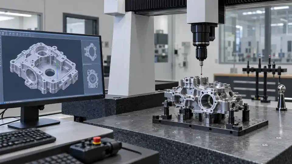
A coordinate measuring machine can report precise-looking numbers and still answer the wrong question. The CMM program must connect the released CAD geometry and drawing requirements to a physical setup, qualified probe, datum alignment, feature-construction rule, sampling strategy, environmental condition, uncertainty, and reporting decision. Importing a model and clicking automatic measurement does not establish that chain.
For a CNC buyer, the important issue is not whether the supplier owns a CMM. It is whether the program evaluates the actual drawing requirement in a reproducible way and records enough context to support acceptance. A part can pass under a best-fit alignment and fail under the functional datum reference frame. A bore can change size depending on point count, depth, filtering, and whether the software constructs a least-squares or envelope-related feature.
This CMM program CNC inspection decision guide explains the questions to settle before first article or production release. It does not replace a metrology specialist’s method, the CMM manufacturer’s requirements, or the governing GPS/GD&T and quality standards.
Start with the Released Requirement
The programmer needs one controlled product definition:
- 3D model and revision;
- 2D drawing or model-based definition with the same revision;
- dimension and geometric-tolerance standard/edition;
- datum targets, datum features, and modifiers;
- material, coating, heat-treatment, and final measurement state;
- characteristic identifiers and required report format;
- sampling and acceptance decision rules;
- any customer-specific inspection method.
Nominal geometry can come from CAD, while tolerances and datums come from the drawing. If those sources conflict, the program must not silently choose one. Stop and obtain a controlled clarification.
An imported STEP AP242 file may carry semantic or graphical PMI, but translator support must be verified. A displayed feature control frame may be only presentation geometry. Confirm that values, modifiers, datum references, and controlled surfaces are machine-interpretable before using them to generate characteristics automatically.
Offline and Online CMM Programming
Offline programming builds and simulates the routine from CAD without occupying the measuring machine. It can reduce CMM downtime, support collision checking, and prepare inspection before the first part arrives. The virtual machine, probe rack, stylus assemblies, fixtures, and software configuration must match the actual cell.
Online prove-out occurs on the physical CMM. The programmer verifies fixture location, probe access, safe clearances, speeds, approach vectors, feature behavior, and report output. Even a well-simulated offline program needs controlled prove-out because cables, clamps, part variation, stylus bending, and actual machine limits may differ.
Record software version, CMM identity, probe/stylus configuration, program revision, CAD/drawing revision, and prove-out approval. A program copied between machines may need requalification.
Datum Alignment: The Most Important Choice
Alignment transforms measured coordinates into the coordinate system used by the drawing. A common plane-line-point alignment constrains six degrees of freedom, but its physical features and order must represent the datum reference frame.
For a planar primary datum, the CMM may measure points on a face and construct a plane. A secondary bore may establish an axis and two translations. A tertiary slot or point may clock the part. The exact construction depends on the callout and governing standard.
Best fit can mask datum error
A best-fit alignment distributes deviations to minimize an objective such as least squares. It is useful for some profile analyses, free-form comparisons, and process diagnostics. It is not automatically the correct acceptance alignment.
If the drawing references A|B|C, aligning all measured geometry by unconstrained best fit can move or rotate the part away from those datums and make a hole pattern look better. The report may then describe closeness to the model rather than conformance to the stated datum frame.
Use datum alignment for acceptance unless the drawing or approved method calls for another evaluation. Best fit can appear as a separate diagnostic, clearly labeled.
Datum feature simulation
Real datum features have form error. The measurement must simulate the intended contact or boundary. Point placement, fitting algorithm, filters, material-boundary modifiers, and datum target locations affect the result.
A least-squares plane through a warped primary face may not represent a surface plate or functional three-point contact. A bore datum at a material boundary may permit datum mobility that a simple centerline alignment ignores. Review the simulation rule and software capability for the actual standard edition.
Probe and Stylus Qualification
The CMM must know the effective size and position of each stylus tip. Qualification measures a calibrated reference sphere or appropriate artifact and determines the stylus geometry used to compensate contact points.
Control:
- probe head and sensor type;
- stylus ball material and diameter;
- stem length/diameter and extension;
- orientation and indexing angle;
- qualification artifact identity and calibration status;
- qualification coverage for all used directions;
- qualification time and environmental state;
- trigger force, scanning settings, and approach speed where applicable.
A stylus qualified in one orientation is not automatically valid after a head index, module change, collision, or extension adjustment. Long styli improve access but increase deflection and dynamic sensitivity. Small balls can enter fine features but are more influenced by roughness and contamination.
Probe access changes the measurement
Deep bores, narrow slots, undercuts, and crowded fixtures may prevent ideal access. The programmer may use star styli, angled tips, extensions, or multiple setups. Each choice adds qualification and correlation needs.
If a feature must be measured in another part orientation, define how the coordinate systems are related. A manual repositioning can add more uncertainty than the feature tolerance allows.
Point Sampling and Distribution
The minimum number of points needed to mathematically construct a feature is not necessarily enough to evaluate the real surface. Three points define a plane, but they cannot describe bow or local waviness. Four points can construct a circle, but they can miss lobing.
Choose sampling from:
- feature size and length;
- expected manufacturing signature;
- required form and location characteristic;
- surface texture and cleanliness;
- probe type and speed;
- tolerance and uncertainty;
- inspection time and production quantity.
Distribute points over the functional zone. Avoid edges, chamfers, burrs, ports, and damaged areas unless they are part of the requirement. For a bore, measure at enough depths and angular positions to detect taper, barrel, bellmouth, or lobing when those conditions matter.
Scanning supplies dense data but introduces filtering, speed, dynamic, and surface-interaction decisions. More points do not repair a wrong datum or unsuitable algorithm.
Feature Construction and Fitting Algorithms
CMM software turns points into substitute features. Common fitting methods include least squares, minimum circumscribed, maximum inscribed, minimum zone, and tangent/contact-related constructions. Different methods can yield different size, location, and form results from the same points.
The algorithm must match the characteristic and applicable standard. Examples:
- An inscribed cylinder may represent a mating pin boundary in a bore better than a least-squares size for certain decisions.
- A minimum-zone evaluation is associated with form characteristics such as flatness or roundness under relevant definitions.
- A tangent plane may represent high-point contact where the callout permits or requires it.
- A constructed midpoint plane or axis needs a defined source feature and association.
Do not accept a report that says only “diameter” or “flatness” when method choice can change the result near the limit. Document the software calculation and verify it against known test cases.
Common Characteristic Blind Spots
Position and bonus tolerance
Position evaluation needs the datum frame, basic location, actual feature size, material-condition modifier, and any datum mobility. The report should distinguish stated tolerance, bonus tolerance, total available tolerance, and measured result. A 2D coordinate shortcut can omit axis orientation and 3D behavior.
Profile
Profile requires correct nominal surface, datum alignment, evaluation boundary, unequal or nonuniform disposition where specified, and appropriate sampling. A global best fit can hide the datum-related error. Make sure trimmed surfaces, CAD patches, and excluded zones match the drawing.
Flatness and parallelism
Flatness is independent of a datum; parallelism is relative to one. A plane constructed from sparse points can understate local form. Supports or clamps can flatten a thin part during measurement.
Runout
Runout evaluates surface variation during rotation about a datum axis. Measuring several circles and reporting cylindricity or concentric location is not automatically equivalent. Confirm software evaluation and physical datum simulation.
Threads
A standard tactile probe generally cannot establish thread pitch-diameter axis by touching an arbitrary cylinder surface. Thread plugs, specialized styli, optical methods, or defined constructions may be needed. State how threaded-feature position is derived.
Surface texture
A CMM is not usually the primary instrument for Ra or Rz. Stylus profilometers or optical texture systems have different filters, cutoffs, and access requirements. Keep dimensional geometry and texture inspection distinct.
Temperature and Material Condition
Dimensional metrology is sensitive to temperature. Material and machine structures expand; gradients bend parts; operator handling warms local areas. The reference temperature, stabilization, and compensation must be appropriate to the tolerance.
Record part and environment temperature when material. Verify the coefficient of thermal expansion used by software and do not apply compensation blindly to a mixed-material assembly. A warm thin aluminum housing and a steel master do not change identically.
The NIST dimensional metrology program provides authoritative context on length measurement and traceability. For the specific job, uncertainty must be evaluated from the actual machine, environment, probe, program, fixture, and feature.
Define whether the part is measured before or after heat treatment, coating, stress relief, cleaning, or assembly. Final acceptance should represent the drawing condition.
Flexible and Thin-Wall Parts
Gravity, supports, clamp force, and probe force can move a flexible part. A CMM program can report the restrained fixture shape rather than the free-state product.
Specify:
- measurement orientation;
- support points or datum targets;
- allowed restraint and force/torque;
- fixture contact surfaces;
- free-state or assembled acceptance;
- stabilization after unclamping;
- probe force and scan strategy.
If the part is functionally bolted flat, an assembly-simulating fixture may be relevant, but the drawing must authorize the condition. Do not invent a restraint to make the part pass.
Measurement Uncertainty and Decision Rules
Every measurement has uncertainty. A suitable process needs uncertainty small enough for the intended decision. Contributors can include CMM performance, calibration, probe qualification, stylus bending, temperature, fixture, alignment, feature form, sampling, software, and repeatability.
A machine specification is not the uncertainty of every reported characteristic. A deep bore measured with a long stylus under a temperature gradient can have a very different uncertainty from a simple gage block length.
For tight or high-consequence requirements, agree on:
- uncertainty evaluation method and scope;
- traceability of standards and artifacts;
- guard band or acceptance decision rule;
- treatment of results near a specification limit;
- correlation between buyer and supplier methods;
- action on significant disagreement.
The standards work of ISO/TC 213 covers dimensional and geometrical product specifications and verification. Use the contractually applicable standards and qualified metrology advice for the actual decision.
Correlate the Program Before Production
Program validation should use more than one good part. Recommended evidence is proportional to risk:
- simulate collision and feature access offline;
- prove the routine at controlled speed;
- measure a representative part repeatedly without repositioning;
- reload the part and repeat to include fixturing/alignment;
- compare selected characteristics with an independent method or artifact;
- challenge near-boundary or known-error features where practical;
- verify report calculations, units, tolerance, and disposition;
- approve the program revision and lock access.
A “golden part” can be useful for monitoring, but it should not become an uncalibrated master whose accepted values drift by convention. Retain traceable reference values and a response plan.
Reporting and Traceability
A useful report identifies:
- supplier and inspection location;
- part number, name, and revision;
- serial/lot/work-order identity;
- drawing/model revision;
- CMM and program ID/revision;
- date and inspector/operator where required;
- units and measurement temperature/condition;
- characteristic or balloon number;
- nominal, upper/lower limit, actual result, and disposition;
- datum reference frame and modifiers for GD&T;
- stated and bonus tolerance where applicable;
- deviation, concession, or exception reference;
- approval status.
An all-green report is not enough if it omits actual values or uses the wrong tolerances. Protect the raw or detailed result data according to the quality plan so a summary can be audited.
The QuickCNCs quality assurance page describes inspection resources. The RFQ should identify which characteristics need actual values, which may be attribute results, and whether a ballooned drawing or first-article form is required.
Match the Sensor to the Feature
A tactile CMM is versatile, but not every characteristic should be forced into contact measurement.
Small holes and narrow slots
The stylus ball and stem must enter without rubbing. A ball that occupies much of the hole can limit point distribution; a thin long stem can bend. Air gaging, pin gages, optical measurement, or a dedicated bore instrument may be more suitable for certain sizes. If the CMM constructs a diameter from only a shallow circle, it may miss taper or bellmouth.
Deep bores
Long extensions increase uncertainty and collision risk. Measure at enough depths to evaluate the required size and form. If the feature is functionally a bearing or seal, the relevant envelope may not be represented by a least-squares cylinder. Consider air gaging, bore gaging, or a dedicated form system for the final decision.
Free-form surfaces
Complex contours need a controlled CAD revision, datum alignment, trim boundary, point or scan distribution, and evaluation direction. Surface-normal deviation, vector deviation, and closest-point deviation are not interchangeable. Define whether profile is unilateral, bilateral, unequally disposed, or nonuniform under the governing standard.
Sharp edges and tiny radii
A finite stylus ball cannot directly reach a mathematically sharp intersection. Software may project adjacent surfaces and construct the edge. The report should identify a derived feature rather than imply direct contact. Burrs and edge breaks can change the construction.
Soft, rough, or fragile surfaces
Probe force can indent polymers, elastomers, thin walls, or delicate finishes. Roughness can add scatter to contact points. Noncontact optical or confocal sensors may help, but their material, reflectivity, calibration, and algorithm limits need validation. A sensor change can require a correlation study.
Internal threads and gears
Thread and gear metrology often requires specialized equipment, software, masters, or defined functional gages. A CMM may evaluate accessible geometry or derived axes, but the buyer should not assume complete thread or gear conformance from a generic dimensional routine.
The method selection should appear in the inspection plan. A supplier may use more than one instrument; the report must make clear which result controls acceptance.
Protect the Program as Controlled Production Data
A CMM routine can change after a CAD update, characteristic addition, fixture adjustment, probe replacement, software upgrade, or bug correction. Control it like other manufacturing data.
Assign a unique program name and revision. Link it to the part and drawing/model revision. Restrict editing, retain approval, and archive the prior released routine. At execution, the operator should be able to verify that the loaded program, report template, fixture, and stylus match the work order.
Define revalidation triggers. A text correction in the report header may need only document review; a changed datum algorithm, probe orientation, sampling pattern, or CAD model needs technical verification. Moving the routine to another CMM requires assessment of machine volume, kinematics, sensor, calibration, environment, and software.
Review automatic updates
Some software can regenerate paths or characteristics when a CAD model changes. That efficiency creates risk if features are re-associated incorrectly or deleted silently. Compare the characteristic list before and after update, verify datum and PMI links, rerun collision simulation, and approve the output. Do not infer equivalence from an unchanged program filename.
Preserve cybersecurity and data authority
Inspection programs can contain customer CAD, geometry, characteristic names, and process details. Store and transmit them under the same access controls as the released product data. Prevent operators from using an unapproved file received through informal email or removable media. Cybersecurity does not require inventing a personal author or customer story; it requires traceable file identity and controlled access.
Investigate Disagreement Between Buyer and Supplier
When two CMMs disagree, do not average the results or choose the more favorable report. Compare the complete methods:
- Confirm part identity, revision, and that the same physical part and surface state were measured.
- Stabilize both environments and record part temperature.
- Compare support, restraint, orientation, and cleaning.
- Compare datum simulation, alignment order, and material-boundary treatment.
- Compare probe/stylus, qualification, speed, and access.
- Compare point locations, density, filtering, and feature construction.
- Compare software standard edition, algorithm, and report units.
- Measure an agreed correlation part or calibrated artifact where relevant.
- Estimate uncertainty and apply the agreed decision rule.
The investigation should identify which method represents the released requirement. A difference inside the combined measurement uncertainty may require a decision rule, while a large systematic difference may expose alignment or construction error. Record the resolution and update both inspection instructions if necessary.
Reduce Inspection Time Without Losing the Decision
CMM cycle time grows with characteristics, points, stylus changes, probe indexing, travel, and report handling. Reduce cost by removing duplication and matching effort to risk—not by deleting the evidence that protects function.
Use the drawing and control plan to classify characteristics. A first article may verify the full product definition, while production inspection focuses on critical, process-sensitive, and change-affected requirements. Stable tool-controlled dimensions may use in-process gages; complex datum-related relationships may remain on the CMM. Approved sampling can reduce repeated work when lot definition and reaction plan are clear.
Optimize safe travel and group features by stylus orientation, but do not change measurement direction or datum behavior solely for speed. Automate report generation and file naming with revision checks. Retain periodic correlation or audit characteristics to detect drift.
CMM Program Review Table
| Program element | Review question | Evidence |
|---|---|---|
| Product definition | Are CAD, drawing, PMI, units, and revision consistent? | controlled file manifest |
| Alignment | Does it simulate the stated datum frame rather than hide error? | setup/alignment definition |
| Probe system | Are all tips/orientations qualified for the used directions? | qualification record and configuration |
| Sampling | Do points/scans reveal expected form and process signatures? | feature strategy and simulation |
| Construction | Does the association/fitting method match the characteristic? | software setting and test case |
| Environment | Are temperature, stabilization, supports, and restraint controlled? | inspection instruction and log |
| Uncertainty | Is the method suitable near the tolerance limit? | uncertainty/decision-rule record |
| Report | Are actual values and traceability tied to the release? | approved report template |
| Change control | Does a model, program, probe, fixture, or machine change trigger review? | revision and revalidation plan |
RFQ Checklist for CMM Inspection
Before quotation, provide:
- controlled model/drawing and governing standard edition;
- characteristic list or ballooned drawing;
- datum, target, and material-boundary definitions;
- final material/finish state and measurement temperature;
- flexible-part support or restraint conditions;
- required actual values, forms, and digital outputs;
- first-article, sample, or 100% inspection scope;
- uncertainty or decision-rule requirements where needed;
- customer form, naming, and approval workflow;
- retention, traceability, and change-control requirements;
- mating or functional information for ambiguous characteristics.
Ask the supplier to identify inaccessible features, special stylus or fixture needs, offline-programming assumptions, and characteristics that require another method.
Approve the Measurement Process, Not the Logo on the Machine
Owning a capable CMM is only the beginning. The accepted result comes from the complete measurement process: released requirement, datum simulation, probe qualification, sampling, construction, environment, uncertainty, and report.
QuickCNCs can review measurement planning alongside its CNC machining services. The related guide CMM Inspection: What Is It and Why Do Your Parts Need It? provides broader context. Submit the model, drawing, quantities, characteristic list, and report needs through the Request a Quote page.
The strongest CMM program is not the one with the most points. It is the one that measures the right characteristic in the right coordinate system, with a qualified method and a report that another reviewer can reproduce.