
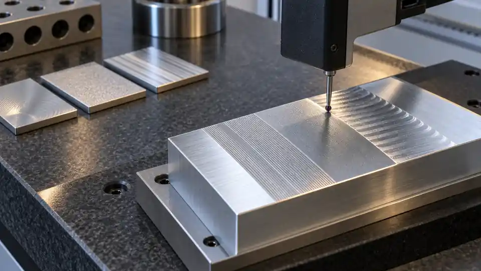
Ra and Rz describe different aspects of a measured surface profile. They are not interchangeable grades, and one cannot be converted reliably into the other with a universal multiplier. A profilometer result also depends on the governing standard, filter, cutoff or nesting index, evaluation length, stylus tip, trace direction, measurement location, and surface condition. A drawing that says only “Ra 0.8” leaves important decisions unstated.
For a CNC buyer, surface-texture acceptance begins before inspection. The drawing should identify the parameter and limit, units, applicable surface, lay if functional, governing standard/edition, and any special measurement conditions. The supplier should confirm that a stylus can reach the surface and that the selected method can separate roughness from waviness and form without removing the signal that matters.
This profilometer Ra Rz CNC guide explains how to plan that measurement. It does not supply a universal cutoff table or replace the controlled standard. ASME B46.1 addresses surface texture under common US practice. The ISO profile framework is now organized in the ISO 21920 series; ISO 21920-2:2021 defines profile terms and parameters. Use the system and edition stated on the drawing.
Ra and Rz Answer Different Questions
Ra is the arithmetic mean of the absolute profile deviations from the mean line over the evaluation basis defined by the applicable method. It summarizes average roughness amplitude. Because peaks and valleys are averaged, a local scratch or isolated deep valley may have limited influence on Ra.
Rz represents a profile-height measure based on peaks and valleys, but the exact definition has varied across national and historical standards. That is why “Rz” without a referenced standard and edition is unsafe. A value reported under one definition may not be equivalent to the same symbol under another.
Two surfaces can have the same Ra but different Rz, spacing, lay, waviness, plateau structure, or isolated defects. Their sealing, friction, wear, lubrication, appearance, fatigue, or bonding behavior can differ.
Do not convert Ra to Rz by rule of thumb
Empirical ratios may describe a controlled family of surfaces made by one process, material, filter, and measurement method. They should not be used as a universal drawing conversion. A turned surface, ground surface, honed plateau, milled face, blasted finish, and polished surface have different distributions.
If function needs both average roughness and peak/valley control, specify and measure both parameters under the same approved standard. If only one is needed, choose it from the functional risk rather than asking for redundant numbers.
Roughness, Waviness, Form, and Defects
A measured trace contains spatial components at different wavelengths:
- form describes large-scale shape such as tilt, curvature, or nominal geometry;
- waviness describes more widely spaced irregularities, often influenced by vibration, deflection, or machine behavior;
- roughness describes finer irregularities associated with cutting, abrasive action, material, and process;
- defects may include scratches, pits, dents, burrs, tears, or contamination that a parameter alone does not adequately represent.
Filtering and the evaluation operator separate these components. A parameter result is therefore not simply the raw vertical motion of the stylus. The selected cutoff can exclude or include wavelengths and change the number.
Do not use a low Ra requirement to control flatness or waviness. Likewise, a surface can meet Ra while containing a functionally unacceptable isolated scratch. Add appropriate form, visual, defect, or functional requirements when those conditions matter.
Cutoff, Nesting Index, and Evaluation Length
Traditional profilometer practice often refers to a cutoff length that separates roughness from longer-wave content. The evaluation length may contain several sampling lengths. Newer standards use a more explicit specification-operator framework, so terminology and default rules depend on the stated standard.
The measurement plan must identify:
- filter type and relevant nesting indices/cutoffs;
- sampling and evaluation lengths;
- number of sampling lengths where applicable;
- traverse length, including run-up and run-down;
- form removal or reference-line treatment;
- parameter calculation and acceptance rule.
A cutoff that is too short can remove surface structure that should contribute. A cutoff that is too long can include waviness or form. If two laboratories use different defaults, their Ra or Rz values can disagree even on the same trace.
Limited-length surfaces
Small sealing lands, narrow grooves, short bosses, and interrupted features may not provide the recommended traverse and evaluation length. Do not silently shorten the measurement and report the result as fully equivalent.
Options include redesigning a witness surface, selecting an approved shorter operator, using an areal/noncontact method, measuring a representative process coupon, or defining another functional test. Any deviation from the drawing method needs engineering approval and should be reported.
Trace Direction Relative to Lay
Lay is the predominant direction of surface pattern. A stylus trace is usually taken in the direction that reveals the relevant profile variation—often perpendicular to lay—unless the specification or function requires another direction.
A turned diameter has circumferential tool marks; an axial trace and a circumferential trace see different structures. A face-milled surface may have curved or crosshatched marks. Grinding and honing produce characteristic directions. A sealing surface can behave differently along and across the leak path.
Mark lay on the drawing when it affects function. In the inspection plan, identify trace direction by a feature reference, not “horizontal on the screen.” For rotational parts, state axial, circumferential, or radial. For prismatic faces, reference datums or edges.
Multiple-direction surfaces
Crosshatch, isotropic blasting, polishing, and multi-axis finishing may not have one simple lay. Use enough traces or an areal method to represent the surface. Do not select the most favorable direction after seeing the results.
Select Measurement Locations Before Inspection
Texture can vary across a machined surface because of tool entry/exit, stepover, cutter engagement, wear, vibration, local stiffness, and finishing overlap. A single trace at the easiest location may not represent the functional zone.
The drawing or inspection plan should identify:
- controlled surface boundaries;
- excluded edges, holes, slots, and transition zones;
- number of locations and distribution;
- orientation at each location;
- whether worst-case visible regions must be included;
- sampling by piece and lot;
- treatment of individual failures versus averages.
For a circular sealing face, use locations around the circumference where access permits. For a long slide or guide, include positions along travel. For a bore, specify depth and angular location. For a cosmetic panel, combine texture measurement with a separate appearance standard.
Stylus Tip, Force, and Access
A contact profilometer uses a stylus tip to follow the surface. Tip radius acts as a mechanical filter: it cannot enter valleys narrower than its geometry. Stylus force can deform soft material, coatings, thin walls, or contamination. Skid and skidless instruments reference the profile differently.
Record:
- instrument and pickup type;
- stylus tip radius and included angle;
- measuring force;
- skid/skidless configuration;
- traverse speed;
- range and resolution;
- fixture and orientation;
- filter/operator settings;
- software version when material.
Deep grooves, small bores, shoulders, and recessed faces may require a special stylus. Verify that the tip—not only the pickup body—can traverse the required length without collision. Long extensions can add vibration and alignment sensitivity.
Curved surfaces
On a cylinder or curved contour, the instrument may need a fixture, radius correction, or form-removal method. Misalignment can introduce curvature or slope into the trace. Specify whether the measurement is axial or circumferential and ensure the instrument’s range and software are suitable.
Cleanliness and Surface Condition
Oil, dust, chips, polishing compound, fingerprints, protective film, and corrosion products can alter a trace or damage the stylus. Clean the surface with an approved method that does not change texture. Avoid abrasive wiping or scraping.
Measure the condition required by the drawing: as-machined, after blasting, after coating, after cleaning, or final assembled state. A pre-coating Ra result does not prove post-coating texture unless the specification explicitly controls the substrate only.
Identify scratches, dents, burrs, and pits separately. Do not repeatedly move the stylus until a local defect is avoided. If a trace crosses a visible anomaly, retain the result and apply the approved defect/parameter decision rule.
Calibration and Verification
Instrument calibration and day-to-day verification serve different purposes. Calibration establishes traceability and performance over defined conditions. Routine checks use a reference specimen or artifact to confirm that the instrument, stylus, settings, and software remain suitable.
Before measurement, verify:
- calibration status and range;
- stylus condition and secure installation;
- reference specimen identity and cleanliness;
- parameter/filter settings;
- instrument leveling and fixture stability;
- repeat result against the control limit;
- environment and vibration;
- software/report configuration.
The reference specimen should exercise the relevant range and parameter. Passing a generic Ra specimen does not prove every Rz, long-trace, or special-stylus configuration.
ISO 12179 addresses calibration of contact stylus instruments under the ISO framework; the applicable lab and contract requirements determine the actual calibration program.
Environmental and Fixturing Effects
Profilometers are sensitive to vibration, movement, and unstable support. Place the instrument and part on an appropriate surface away from machine vibration and airflow. Secure the part without distorting a thin feature.
Temperature has less direct effect on micrometer-scale roughness than on large dimensional measurements, but it can influence instrument stability, part expansion, and soft materials. Allow cleaned or processed parts to reach the defined condition.
For a vertical, internal, or large surface, portable instruments may be used. Confirm orientation capability and fixture rigidity. Gravity and pickup mounting can affect some systems.
Ra and Rz Acceptance Rules
State whether the requirement is a maximum, minimum, or range. Many drawings use a maximum roughness; lower is not always automatically better. A very smooth surface can reduce lubricant retention, change seal run-in, or impair adhesion.
Define how multiple traces are evaluated. Options may include every trace meeting the limit, a specified maximum number of nonconforming sampling lengths under a standard rule, or an approved statistical plan. Do not average away a local failure unless the specification permits it.
Report the actual values with units and parameter symbol. Micrometers and microinches differ by a factor of 25.4. A report that lists “0.8 Ra” without units is incomplete.
Measurement Plan Table
| Control item | Drawing/RFQ input | Inspection record |
|---|---|---|
| Parameter | Ra, Rz, or other defined parameter | exact symbol and value |
| Standard | governing document and edition | applied standard/operator |
| Limit | maximum, minimum, or range | nominal/limit and disposition |
| Units | µm or µin | explicit units on every result |
| Surface | controlled zone and exclusions | location/feature identifier |
| Lay/direction | required lay and trace orientation | actual trace direction |
| Filtering | cutoff/nesting index and filter | instrument settings |
| Evaluation | sampling/evaluation/traverse lengths | lengths and number of traces |
| Stylus | access and required tip configuration | tip, force, pickup, speed |
| Condition | as-machined or final process state | cleaning, coating, temperature |
| Sampling | pieces, locations, frequency | serial/lot and trace results |
This table prevents a parameter value from becoming separated from the method that gives it meaning.
CNC Process Signatures
Turning
Feed per revolution, nose radius, tool condition, material, vibration, and built-up edge influence the helical profile. Theoretical geometry can estimate an idealized finish, but actual material behavior and machine dynamics must be measured. A short axial trace is commonly informative; verify lay and access.
Milling
Feed per tooth, cutter runout, insert height, stepover, entry/exit, toolpath overlap, and part stiffness create direction-dependent texture. Face milling and end milling produce different patterns. Choose trace locations that do not sample only a favorable pass.
Grinding
Wheel specification, dressing, speed, feed, coolant, spark-out, loading, and burn affect texture. A low Ra does not prove absence of grinding burn or tensile damage; add appropriate process or integrity checks when required.
Honing and lapping
Plateau and crosshatch surfaces may need parameters beyond Ra/Rz to represent load-bearing area and valleys. State the functional parameter set and standard; do not reduce a cylinder-liner or seal surface to one average number.
Blasting and polishing
Random or multi-directional texture may be better represented by multiple traces or areal measurement. Cosmetic appearance also depends on gloss, color, directionality, and defects that profilometry does not capture alone.
Correlate Different Instruments and Sites
Buyer and supplier results can differ because of standards, styli, filters, trace locations, cleaning, and software. When correlation matters, measure the same identified areas on the same artifact under agreed settings.
Compare:
- parameter definition and standard edition;
- units and limits;
- cutoff/nesting index and filter;
- evaluation and traverse length;
- stylus tip, force, skid, and speed;
- trace direction and location;
- cleaning and final surface state;
- calibration/reference specimen;
- result calculation and acceptance rule;
- measurement uncertainty.
Do not “correct” one laboratory with an unsupported offset. Resolve the method difference and retain the correlation record.
Contact Versus Optical and Areal Methods
Optical profilometry and areal surface-topography methods can capture dense 3D information without a contact stylus. They can be valuable for delicate, very small, steep, structured, or directionally complex surfaces. Results depend on optical principle, reflectivity, slope, focus, filtering, missing-data treatment, and areal parameter definitions.
Areal parameters such as Sa and Sz are not direct replacements for profile Ra and Rz. If the drawing specifies a profile parameter, an optical areal result needs an approved correlation or requirement change. ISO 25178-2 defines areal surface-texture terms and parameters within the ISO framework.
Use the method that represents function and can be controlled in production. Record the method explicitly.
Common Specification and Inspection Errors
Ra is substituted for Rz
The supplier reports an average roughness when the drawing controls a peak/valley parameter. Measure the specified parameter or obtain an engineering change.
Units are omitted
The numeric result cannot be interpreted reliably. Require µm or µin in the drawing and report.
Default cutoff is used without review
Instrument auto-selection may not match the drawing or surface. Record the selected operator.
Trace runs along the lay
The result can underrepresent the profile seen across machining marks. Define orientation before measurement.
The easiest location is measured
Entry/exit, corner, wear, or sealing zones are missed. Use a planned location map.
A visible scratch passes because Ra is low
Average roughness does not replace defect acceptance. Add visual or defect criteria.
Pre-finish and post-finish results are mixed
Blasting, coating, polishing, or cleaning changes the surface. Report the controlled final state.
RFQ Checklist for Surface Texture
Before quotation, provide:
- parameter symbol and maximum/minimum/range;
- units;
- governing standard and edition;
- controlled surface and excluded zones;
- lay requirement and trace direction;
- cutoff/nesting index and filter when not defined by an accepted default;
- sampling/evaluation length and limited-length exception;
- number and distribution of trace locations;
- final process and cleaning condition;
- special stylus/access needs;
- lot and piece sampling plan;
- actual-value report and calibration requirements;
- separate cosmetic or defect acceptance criteria;
- functional context for sealing, wear, lubrication, bonding, or appearance.
Select Parameters from the Functional Surface
Ra and Rz are common because they are widely understood and measured, but neither alone describes every function. Review the contact mechanism before adding parameters.
Sealing surfaces
A seal can be affected by roughness amplitude, waviness, lay direction, scratches, porosity, and the path that connects pressure to atmosphere. A low Ra measured across one short trace does not prove leak tightness. Define lay, permitted defects, flatness or form, and a leak/pressure test when the assembled function requires it.
Sliding and bearing surfaces
Friction and wear depend on peaks that carry load and valleys that retain lubricant. A plateau-honed surface may need material-ratio or other functional parameters in addition to an average height. Specify them only with an appropriate standard and validated measurement method.
Adhesive, coating, and paint preparation
Bonding can require enough texture for mechanical keying without contamination, weak surface layers, or peaks that prevent intimate contact. The approved pretreatment, cleanliness, surface energy, and process window can matter more than a generic Ra maximum. Coordinate the substrate texture with the coating or adhesive supplier.
Optical and cosmetic surfaces
Appearance depends on spatial wavelength, direction, gloss, reflectivity, color, and viewing conditions. A stylus trace samples a very small path and may miss a visible machining pattern. Combine objective texture parameters with a controlled visual or optical method where appearance is contractual.
Fatigue-sensitive surfaces
Surface condition can influence fatigue through notches, scratches, tensile residual stress, and process damage. Ra alone cannot demonstrate residual stress or absence of grinding burn. Apply the material/process integrity requirements supported by the design basis.
The drawing should not accumulate every available parameter. Choose the smallest set that distinguishes an acceptable functional surface from a harmful one.
Model Profilometer Inspection Cost
Texture inspection cost includes more than the seconds of stylus travel. The supplier may need engineering review, a special stylus, part fixture, calibration/reference checks, cleaning, environmental setup, multiple locations, data export, and report approval.
Separate:
- nonrecurring method and fixture development;
- per-batch setup and reference verification;
- per-piece loading, alignment, and measurement;
- repeated traces and multiple parameters;
- special access or portable-instrument work;
- correlation or uncertainty studies;
- customer-form and data-retention requirements.
At prototype quantity, a comprehensive surface report may carry significant NRE. At production, qualified sampling or a process-monitoring plan may reduce per-piece inspection if the product risk permits. Do not assume a low Ra value automatically requires 100% measurement, and do not reduce sampling without a lot definition and reaction plan.
Ask the supplier to identify which requirement drives inspection time: limited access, many locations, long evaluation lengths, several parameters, or final-process handling. A targeted drawing callout often reduces cost more effectively than negotiating the measuring rate.
Preserve Raw Traces When the Decision Is Sensitive
A summary report can hide filtering, local defects, and parameter variation. For first article, correlation, or a disputed result, retain the raw profile or instrument-native data, setup image, location map, and parameter settings. Protect file identity and software version.
Raw data allows a qualified reviewer to check whether an edge, scratch, outlier, or form-removal choice changed the result. It also supports reanalysis if the drawing requirement is clarified. Retention does not mean every production trace must be stored indefinitely; define scope and period from contract and risk.
Specify the Measurement Along with the Number
QuickCNCs supports machining and surface finishing, including inspection planning for applicable parts. The related article on quality control methods for precision machined parts provides broader inspection context.
To request a quotation, submit the controlled model and drawing, material, quantity, final finish, surface-texture definition, measurement locations, reporting, and delivery needs through the Request a Quote page.
A trustworthy Ra or Rz result carries its method with it. The parameter, standard, filter, length, direction, location, stylus, condition, and decision rule must all describe the same functional surface. That is what turns a small decimal on a drawing into reproducible manufacturing evidence.