
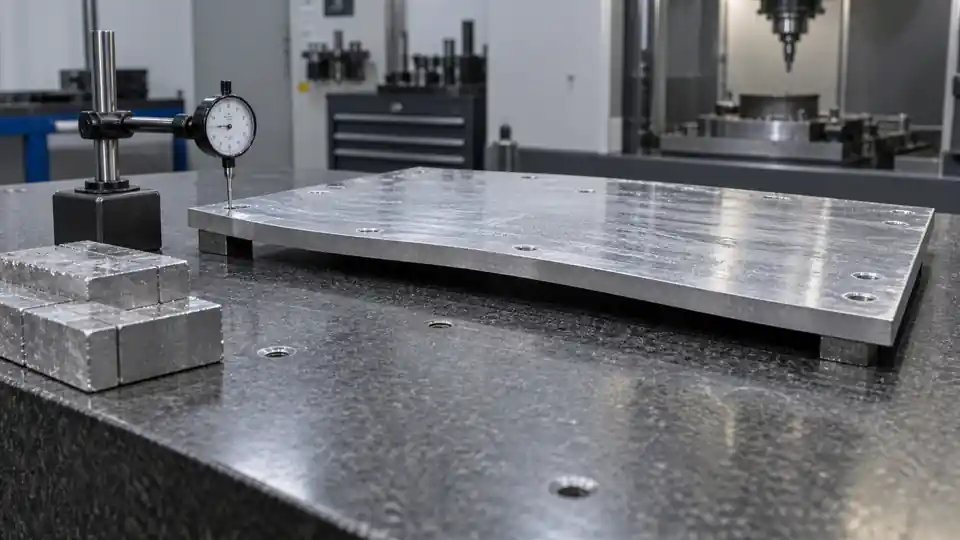
A plate that measures flat while clamped can bow as soon as it is released. Another part can leave the machine flat and move during inspection, anodizing, temperature stabilization, or shipping. “Warp” describes the symptom, not the cause. Corrective action depends on whether the distortion originates in incoming stock, residual stress released by cutting, unbalanced geometry, clamping, heat, datum strategy, finishing, or measurement.
The most useful investigation starts with when the shape changes. Measure the blank before machining, the workpiece after roughing, the part while restrained, the part immediately after release, and the part after stabilization. This timeline separates a material problem from a fixture or inspection problem.
This warped CNC plate root cause decision guide gives buyers and engineers a structured diagnostic path. It does not promise a universal flatness capability. Actual behavior depends on material, temper, product form, size, geometry, process, tolerance, and final measurement state.
First Define What “Warped” Means
Use the drawing characteristic rather than a visual description. Possible symptoms include:
- overall flatness error on one face;
- bow or dish across the plate;
- twist between corners;
- loss of parallelism between faces;
- local waviness near pockets, ribs, or clamps;
- thickness variation mistaken for flatness;
- profile error of a thin frame;
- movement relative to datums after unclamping;
- assembly gap or rocking on a mating surface.
Flatness is a form control independent of a datum. Parallelism compares a surface to a datum. Profile may control a contoured or planar surface relative to a datum frame. An assembly-gap problem may involve both components and their fasteners. Diagnose the requirement actually failed.
State the measurement condition
Define whether the part is measured free-state, under its own weight on supports, lightly restrained, or assembled with specified fasteners and torque. Thin plates can change under gravity or contact force. A report without support points, orientation, temperature, and restraint can be impossible to reproduce.
If assembly flattens the part, engineering must decide whether free-state flatness is still required. Do not let the supplier assume that mounting will correct the part unless the drawing permits that condition and the assembly has enough stiffness without damage.
Root-Cause Decision Tree
Use this sequence before changing feeds, adding a heat treatment, or rejecting stock.
- Was the incoming blank already outside its agreed flatness/straightness condition? If yes, investigate stock form, cut method, thickness tolerance, storage, and supplier acceptance.
- Does the part change mainly when clamps are applied or released? If yes, investigate fixture distortion, datum support, clamping force, chip under supports, and thin-wall stiffness.
- Does it move progressively as material is removed? If yes, investigate residual stress, asymmetric stock removal, and geometry balance.
- Does the result correlate with cutting temperature or inspection timing? If yes, investigate thermal gradients, coolant, dwell, and measurement stabilization.
- Does it move during heat treatment or surface finishing? If yes, investigate process sequence, support/racking, coating, quench, stress relief, and post-process stock.
- Do different measurement setups disagree? If yes, investigate support, datum alignment, gravity, probing force, point strategy, and temperature.
- Does the part change during storage or shipping? If yes, investigate relaxation, packaging restraint, stacking, environment, and time-dependent material response.
Several branches can be active at once. Evidence should identify the contribution of each before corrective action is closed.
Incoming Stock Stress and Flatness
Plate, sheet, bar, extrusion, forging, casting, and polymer shape carry different processing histories. Rolling, extrusion, quenching, stretching, straightening, sawing, flame cutting, and prior machining can leave residual stress. The blank may also be bowed before machining.
Record incoming:
- material grade and exact temper/condition;
- product form and governing specification;
- heat/lot and certificate identity;
- mill thickness and purchased size;
- blank cutting method and orientation;
- initial flatness/bow/twist on defined supports;
- surface condition and damaged areas;
- storage orientation and time after cutting.
For aluminum, a stress-relieved temper such as T651 plate may reduce certain residual-stress risks compared with a broader T6 callout, but it does not guarantee a flat heavily pocketed part. The QuickCNCs CNC machining materials page provides material context; the RFQ should specify the exact grade, temper, and product form.
Sawing and profile cutting can release stress
A large plate can change after a blank is cut from it. Waterjet, laser, plasma, or flame cutting may introduce or release additional stress depending on material and method. Leave enough margin to create stable machining datums, and inspect the cut blank rather than relying only on mill plate data.
If an edge is cut close to the final part, local movement may consume the cleanup allowance. The supplier should state its proposed blank size and cutting route.
Unbalanced Material Removal
When most stock is removed from one face or one side, the remaining stress distribution and stiffness become asymmetric. Deep pockets, one-sided ribs, thin floors, and large open frames are common triggers.
Compare removed volume by region and by stage. A process can reduce movement by roughing both faces, flipping the part, alternating sides, and leaving consistent finish stock. The goal is not geometric symmetry for its own sake; it is a balanced sequence that preserves enough stiffness while residual stress is released.
Rough, rest, and finish
A typical high-risk route may:
- create reference faces with conservative stock;
- rough major pockets and outside geometry from both sides;
- release clamps and allow the part to stabilize;
- re-establish datums on the relaxed part;
- semi-finish critical features;
- repeat stabilization or approved stress relief if needed;
- finish both sides and final datums;
- inspect after temperature and time are controlled.
“Rest” is not a magic time. The appropriate interval depends on material, process, geometry, temperature, and production needs. Ask the supplier what change is expected and how it is verified.
Clamping Distortion
A warped blank can be forced flat against a fixture. The machine then cuts it flat in the restrained condition; after release, it returns toward its original shape. The reverse can happen when clamps bend a thin floor and the cutter machines the deflected surface.
Check:
- number and location of support points;
- primary datum contact and whether the part rocks;
- clamp direction and magnitude;
- support directly beneath clamp loads;
- vise jaw parallelism or vacuum-plate flatness;
- chips, burrs, or raised marks under the part;
- adhesive or vacuum pressure and release behavior;
- residual tabs or sacrificial stock;
- workholding change between rough and finish stages.
Use the minimum force that resists cutting without distorting the component. Hydraulic, pneumatic, and manual clamps need controlled force or procedure. A torque value at a clamp screw does not translate directly into known part deformation without fixture-specific validation.
Three-point support and overconstraint
Three noncollinear points define a plane. Additional supports can improve stiffness but may overconstrain a bowed part if they are not adjustable or coplanar. Fixtures for thin plates often use qualified support pads, jack screws, vacuum zones, or low-force clamps to support cutting loads without forcing a false shape.
The inspection fixture can create the same problem. Aligning a CMM to a best-fit plane is not equivalent to simulating the drawing datum. Document the support and alignment.
Thermal Drift During Machining
Cutting energy, spindle growth, warm coolant, room changes, and operator handling create temperature gradients. A large plate can be warmer near a deep pocket or at the machine-contact face. When it cools, both size and shape can change.
First-order linear expansion is often screened with:
ΔL = α × L × ΔT.
The equation estimates uniform dimensional change; it does not predict distortion from a nonuniform temperature field. A gradient through thickness can bend a plate even when average temperature is near target.
Control options include stable coolant temperature, balanced roughing, reduced heat input, dwell, in-process temperature checks, and inspection after stabilization. Do not chase a warm dimension with an offset that creates an error after cooling.
Toolpath and Cutting-Force Effects
Tool deflection and wall movement can look like global warp. Heavy cuts near a thin edge may pull or push the wall. An aggressive finishing pass can leave taper or a scalloped plane. Tool wear or built-up edge can increase force over the batch.
Review cutter diameter, engagement, tool reach, entry/exit, climb/conventional direction where relevant, stock consistency, and part support. Leave uniform finish allowance. Avoid finishing a critical face immediately after a high-heat roughing operation if the part has not stabilized.
In-process probing can detect movement relative to the machine, but a probed surface may also be deflected by clamps. Compare in-fixture and free-state results.
Geometry and Stiffness
Thin uniform plates, window frames, large pockets, interrupted ribs, and abrupt section changes respond differently. Improve stiffness where function permits:
- use ribs rather than broad thick regions;
- avoid one heavy boss on an otherwise thin floor;
- smooth thickness transitions;
- preserve a temporary web or frame during roughing;
- add sacrificial clamp tabs outside the finished envelope;
- split a very thin monolithic part into a stable assembly when acceptable;
- move nonfunctional pockets or balance material removal;
- relax flatness only if assembly and sealing allow.
Every change must be checked for weight, fatigue, vibration, heat transfer, sealing, cleaning, and assembly. The shop proposes DFM options; engineering controls the product definition.
Stress Relief and Heat Treatment
Thermal stress relief can reduce residual stress for suitable materials and conditions, but it can also change hardness, properties, scale, corrosion behavior, and dimensions. It must be compatible with the alloy, temper, customer specification, and final function.
Decide whether stress relief occurs at the mill, before roughing, after roughing, or between semi-finish and finish. Leave stock for movement. Define support in the furnace, heating/cooling control, required certificate, and post-process inspection.
For heat-treated steels, rough-soft/heat-treat/finish-hard is common when final properties and tight geometry are required. Grinding or hard milling may establish final faces. For precipitation-hardened alloys, aging sequence and starting condition matter. Do not add an unspecified heat cycle as a shop-floor correction.
Surface Finishing and Outside Processing
Anodizing, plating, blasting, polishing, passivation, paint, and cleaning can change measured condition or damage a thin part through racking and handling. Coating buildup can affect parallelism and contact. Blasting or polishing can remove material nonuniformly. Chemical or thermal exposure may release stress.
Define final dimensions and flatness as pre- or post-finish. Identify masking, rack/contact areas, and how the part is supported. Reinspect affected characteristics after processing.
If a part is flattened temporarily for racking and springs back, the finished result may differ from the machine-shop inspection. Carry the measurement condition through the sub-tier instructions.
Inspection Method Can Create or Hide Warp
Support, gravity, probe force, and alignment affect thin plates. A granite-surface check, CMM scan, optical method, and assembled fixture can produce different answers if conditions are not equivalent.
Define:
- support points and orientation;
- free-state or restrained condition;
- restraint force/torque and sequence if used;
- time and temperature stabilization;
- surface sampling density and excluded edge zones;
- filtering and fitting method;
- datum simulation for parallelism/profile;
- whether actual-value maps are required.
A few probe points can miss local waviness. A dense scan can reveal texture or edge roll that is not functionally relevant. Match sampling to the drawing definition and mating interface.
The QuickCNCs quality assurance page describes inspection capabilities. The RFQ should specify the condition and report needed for this part.
Evidence Table for Root-Cause Isolation
| Observation | Likely branch | Evidence to collect | Next controlled test |
|---|---|---|---|
| Blank bowed before cutting | incoming stock/cut release | stock condition, cut map, initial surface map | compare alternate stock form or blank orientation |
| Flat while clamped, warped after release | fixture distortion or residual stress | in-fixture and free-state measurements, clamp sequence | reduce/relocate force or rough and re-datum |
| Movement grows with pocket depth | unbalanced removal | measurements after each roughing stage | alternate sides and leave balanced stock |
| Different immediately vs after cooling | thermal gradient | part/coolant/room temperatures and time | stabilize before offset and inspection |
| Moves after heat treatment | thermal process and allowance | furnace lot, support, hardness, before/after map | revise sequence or finish stock |
| CMMs or setups disagree | measurement condition | supports, alignment, points, temperature | controlled correlation study |
| Changes during storage/shipment | relaxation or packaging | time series, stacking, restraint, environment | qualified packaging and stabilization |
Do not close the issue with “operator error” or “material stress” without evidence that distinguishes these branches.
Corrective Actions by Cause
Incoming stock
Tighten or clarify product form and temper, increase cleanup allowance, qualify the cut method, change blank orientation, or inspect stock before committing machining time.
Residual stress and removal balance
Rough both sides, sequence removal, leave uniform finish stock, add stabilization, or use an approved stress-relief route. Change material/product form if evidence supports it.
Workholding
Correct support, reduce clamping force, add controlled jacks or vacuum zones, preserve temporary stiffness, and verify the fixture surface. Clean every locating interface.
Thermal behavior
Stabilize coolant and environment, reduce heat concentration, separate rough and finish stages, record temperatures, and inspect after defined equilibration.
Design stiffness
Add ribs, improve thickness transitions, rebalance pockets, create assembly-compatible relief, or revise the free-state requirement if function permits.
Measurement
Define supports, gravity orientation, datum alignment, scan strategy, restraint, and temperature. Correlate methods with the functional assembly.
Quote and Lead-Time Impact
Warp risk adds cost through stock selection, larger blanks, balanced multi-setup roughing, stabilization time, heat treatment, fixtures, probing, finish machining, surface mapping, and scrap exposure. It adds calendar time through rest periods and outside processing.
Ask the supplier to identify:
- proposed stock grade, temper, form, and blank size;
- rough/semi-finish/finish sequence;
- number of unclamp and re-datum events;
- fixture and clamp strategy;
- thermal/stabilization controls;
- stress relief or heat treatment;
- final-condition measurement method;
- assumptions that drive risk allowance;
- DFM alternatives and expected technical effect.
Compare routes at the same free-state requirement, finish condition, quantity, and inspection scope. A lower quote may simply assume the plate can be forced flat during inspection or assembly.
Material-Specific Diagnostic Clues
Aluminum plate
Check alloy, temper, plate thickness, rolling direction, and whether the temper includes a recognized stress-relief practice. Heavy one-sided pocketing and thin floors are frequent concerns. Aluminum also responds quickly to thermal changes, so compare warm in-machine results with stabilized free-state measurements. Do not assume a generic T6 callout represents the intended plate condition.
Stainless and alloy steel
Bar and plate may carry stress from rolling, straightening, cold work, or prior thermal treatment. Austenitic stainless can work harden locally; hardened steels may move during quench, temper, or grinding. Record the supply condition and final heat-treatment route. If scale or decarburization must be removed, include adequate machining allowance.
Tool and mold steel
Large blocks can require roughing, stress relief, heat treatment, straightening, and finish machining. Deep cavities and uneven section thickness affect distortion. Define final hardness, heat-treatment specification, stock allowance, and which datums survive the thermal cycle. A prehardened route may avoid one heat-treatment step but changes machinability and available condition.
Titanium and nickel alloys
Lower thermal conductivity and high cutting loads can create local heat and deflection. Expensive stock makes scrap exposure significant. Use conservative tool access, stable workholding, and controlled rough/finish sequencing. If a near-net forging is considered, compare its own residual-stress and qualification requirements.
Engineering plastics
Polymer plates and shapes can contain manufacturing stress, absorb moisture, creep under clamps, and change with temperature. Fiber-filled materials may be directional. Define conditioning, storage, measurement temperature, moisture state, and time after machining. A part that is flat immediately after release may move as it equilibrates.
These clues guide testing; they are not a substitute for material-specific data or an actual process trial.
Run a Controlled First-Article Distortion Study
For a high-risk plate, convert the first article into a process-learning plan. Choose measurement stages before machining begins so data is comparable:
- Map the incoming blank on defined supports and record temperature.
- Measure after the first facing or datum operation.
- Measure after major roughing while clamped and again after release.
- Record the time-dependent change after a defined stabilization interval.
- Repeat after semi-finishing, heat treatment, or stress relief.
- Map the final part before and after surface finishing.
- Verify the functional assembly or fixture condition when relevant.
Use the same coordinate convention and identify support points on every map. Retain stock-removal state, clamp locations, program revision, material heat/lot, and inspection method. A colored deviation map can help visualize bow and twist, but the underlying numeric data and datum definition must remain available.
If the study shows that movement enters after release from a particular setup, test one controlled change at a time: clamp force, support, roughing balance, stabilization, or stock condition. Changing the material, toolpath, fixture, and inspection method together can produce a better part without revealing which correction worked.
Define the production reaction plan
After the first article, set in-process signals that can detect drift early. These may include blank flatness, material/heat identity, a post-rough free-state check, part temperature, clamp-force setting, or a limited surface map. Define when production stops, what quantity is contained, who reviews the data, and which steps require revalidation.
The reaction plan should scale with risk. It should not force a full CMM map after every routine operation when a simpler in-process check predicts the final result. Conversely, one successful first part does not prove an uncontrolled setup will remain stable across material lots and repeat releases.
RFQ Checklist for Distortion-Sensitive Plates
Provide:
- controlled 3D model and drawing revision;
- material grade, temper/condition, and product form;
- overall size, minimum wall/floor, pockets, ribs, and section changes;
- functional mounting, sealing, and load interfaces;
- flatness, parallelism, profile, and thickness requirements by surface;
- free-state or restrained measurement definition;
- coating, heat treatment, and final dimensional state;
- permitted straightening or stress-relief methods;
- actual-value surface map or report requirement;
- prototype, batch, and annual quantity;
- packaging/support requirements for thin parts;
- mating component information where assembly can influence shape.
Close the Loop with a Timeline
When a plate warps, preserve measurements from each process state rather than inspecting only the final symptom. Compare blank, rough, released, stabilized, heat-treated/coated, and final conditions. Record fixture, temperature, time, lot, and revision.
QuickCNCs can review process sequencing for prototypes and low-volume CNC machining. Submit the controlled model, drawing, material condition, quantities, finishing, flatness/measurement state, and available distortion evidence through the Request a Quote page.
The goal is not to guarantee that a thin heavily machined plate never moves. It is to define the functional condition, find when movement enters the route, apply the corrective action to the supported cause, and verify the final part in a reproducible state.