
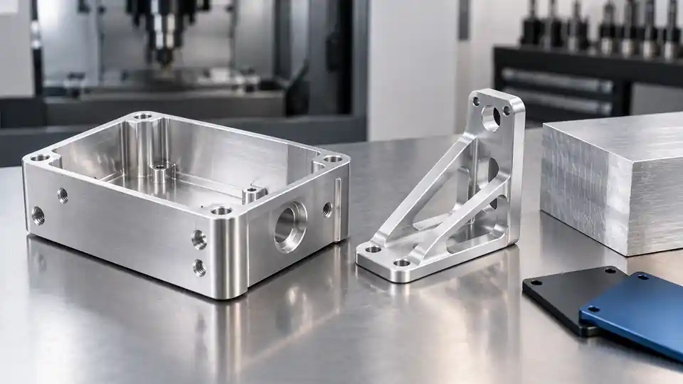
6061-T6 aluminum is a common starting point for machined housings and brackets because it combines availability, moderate strength, corrosion resistance, thermal conductivity, low density, machinability, joining options, and finish compatibility. It is not the automatic best alloy. Stiffness, fatigue, high-temperature strength, wear, threads, electrical behavior, stress-corrosion exposure, and raw-stock form can make another material more suitable.
This 6061 T6 precision CNC housing decision guide helps buyers connect the alloy and temper to actual part requirements. It also explains why “6061” is incomplete on an RFQ, how plate, bar, extrusion, and forging differ, and how machining and finishing affect dimensions.
What 6061-T6 Means
6061 is a wrought aluminum-magnesium-silicon alloy designation. The T6 temper indicates solution heat treatment followed by artificial aging under a defined route. Material specifications establish chemical composition, mechanical-property limits, product forms, tolerances, and certification rules.
The complete purchasing callout needs more than the alloy and temper. Identify:
- governing material specification and revision;
- alloy and temper/condition;
- product form: plate, sheet, bar, extrusion, tube, or forging;
- dimensions and any special stock tolerances;
- grain direction or orientation where relevant;
- producer or source approval if required;
- heat/lot traceability and test report;
- ultrasonic or other additional testing when invoked; and
- substitution authority.
Properties vary with product form, thickness, orientation, heat treatment, and specification. Use certified values for design and acceptance rather than a generic web table.
Why Designers Choose It
6061-T6 is attractive when a component needs a balanced set of properties rather than an extreme one. It machines well with appropriate aluminum tooling, is widely stocked in many forms, accepts anodizing and conversion coatings, and can often be welded with suitable design and post-weld property assumptions.
For housings, it can provide lightweight structure, heat spreading, electrical continuity at controlled contacts, corrosion resistance in many environments, and economical removal from billet or plate. For brackets, it supports pockets, ribs, bosses, threaded inserts, dowels, bearing interfaces, and cosmetic finishing.
The Aluminum Association’s standards overview notes that alloying affects strength, density, workability, conductivity, and corrosion, and identifies 6061 as a widely used 6xxx-series alloy. Use its registered alloy/temper data and the applicable purchased specification for final requirements.
Strength Is Only One Selection Axis
6061-T6 has moderate structural strength, but a material decision should evaluate:
- yield and ultimate strength in the relevant direction;
- elastic modulus and required stiffness;
- fatigue spectrum and stress concentration;
- fracture or impact behavior;
- bearing and thread loads;
- service temperature and thermal exposure;
- corrosion and galvanic coupling;
- wear and sliding contact;
- electrical/thermal conduction;
- manufacturing distortion; and
- regulatory or customer material restrictions.
A stronger alloy does not make a bracket stiffer at the same geometry if elastic modulus is similar. Increasing section depth, adding ribs, or shortening load paths may improve deflection more efficiently than changing alloy.
Keep strength and stiffness calculations separate
Document the load case that controls each decision. Yield margin, elastic deflection, joint slip, bearing stress, and fatigue can point to different design changes; a single material “strength” number does not settle them.
Stiffness and Natural Frequency
Housings and brackets often fail a deflection or vibration requirement before they reach material yield. Use geometry, modulus, boundary conditions, joint compliance, and load location to estimate stiffness. Thin covers, long cantilevers, open sections, and large pockets can dominate.
For equal geometry, common aluminum alloys have broadly similar elastic modulus. Switching from 6061 to a higher-strength aluminum may allow thinner sections, but the resulting stiffness must be recalculated. If geometry cannot change, steel or another higher-modulus material may be required, with density and corrosion tradeoffs.
Prototype tests should reproduce fastener preload, mating stiffness, temperature, and loads. A rigid fixture can make the bracket appear stiffer than the installed system.
Thermal Performance
6061 is often selected for electronics housings, heat spreaders, cold plates, and optical/mechanical frames because aluminum conducts heat and has relatively low density. Thermal performance still depends on alloy/temper, temperature, section, interface flatness, contact pressure, thermal interface material, coatings, airflow or coolant, and heat source distribution.
NIST publishes a 6061-T6 thermal and elastic property reference for cryogenic-to-ambient research, including thermal conductivity, specific heat, modulus, and expansion. NIST warns that the page is no longer updated, so use it as a reference trail rather than current purchasing acceptance data.
Coefficient of thermal expansion matters across temperature. A 6061 housing joined to steel, glass, ceramic, PCB, or optical components can move differentially. Locate datums and clearances around actual thermal paths.
Corrosion and Environmental Limits
6061 performs well in many atmospheric applications, especially with an appropriate finish, but “corrosion resistant” is not universal. Chlorides, crevices, trapped fluids, dissimilar-metal contact, cleaners, high temperature, and damaged coating can change behavior.
For galvanic couples, consider material potentials, electrolyte, area ratio, contact, and drainage. Isolate or seal dissimilar metals where appropriate. Do not allow anodize to be the only electrical bond path if grounding is required; define masked contact areas and conversion coating or other protection.
For marine, chemical, vacuum, medical, or regulated environments, obtain material/finish compatibility evidence specific to the exposure.
Product Form Changes the Starting Condition
Plate, bar, extrusion, and forging are not interchangeable pieces of “6061-T6.” They carry different dimensional tolerances, grain flow, residual stress, mechanical-property directions, surface condition, minimum order, and availability.
Plate or rectangular bar is common for machined housings. Extrusion can reduce material removal for long constant sections but requires die cost/availability and produces profile-specific tolerances and grain flow. Forging can improve near-net shape and directional properties at volume but adds tooling. Rolled plate and drawn/extruded bar can behave differently as material is removed.
Match the raw-stock callout to the design analysis and supplier quote. If the supplier may choose form, require an approved substitution review.
Trace form and temper into receiving records
Receiving should match the purchase order, stock marking, certificate, and traveler before cutting. If a plate certificate or temper is wrong, quarantine the blank while traceability still exists instead of discovering the mismatch after machining.
T6, T651, and Stress-Relieved Conditions
Large plate is often purchased in a stress-relieved temper such as T651, depending on product specification. The added designation matters because controlled stretching after heat treatment can reduce residual-stress distortion compared with an unstress-relieved condition.
Do not casually change T6 to T651 or vice versa. Check the applicable specification, form, thickness, mechanical properties, straightening, and design authority. Put the intended temper on drawing, purchase order, material certificate, and receiving record.
For deep-pocketed or asymmetric housings, select stable stock and a balanced machining plan even when stress-relieved material is used. No temper eliminates all movement.
Machinability and Cutting Strategy
6061-T6 generally machines cleanly with sharp, polished tools, suitable geometry, chip evacuation, stable workholding, and coolant/lubrication appropriate to the process. Aluminum can form built-up edge if tooling or conditions are poor.
Plan:
- stock allowance and datum sequence;
- roughing that distributes material removal;
- chip evacuation from deep pockets;
- wall support and fixture contact;
- rough/finish separation;
- tool reach and corner radii;
- burr access and edge-break definition;
- thermal stabilization before final inspection; and
- protection of cosmetic faces.
High material-removal rate can make 6061 economical, but thin walls and large plates still distort if the route releases stress or clamps the part unnaturally.
Distortion in Housings and Plates
Pockets remove the core that balanced the stock. A thin floor or open frame can move when unclamped. Asymmetric material removal, poor stock flatness, excessive clamping, cutting heat, and finish sequence add risk.
Mitigation may include stress-relieved stock, oversize blank, symmetric roughing, staged release, intermediate rest/stabilization, fixture contact near datums, low-force finishing, flipping, and final measurement in free state.
Specify flatness and profile in the correct state. If the assembly legitimately restrains the housing, define the restraint and datum scheme rather than letting the supplier invent it.
Thin Walls, Ribs, and Bosses
Thin walls save mass but reduce stiffness during machining and service. Tool pressure and vibration can deflect the wall; unclamping can reveal shape change. Very tall thin ribs limit cutter access and chip evacuation.
Use generous internal radii, consistent wall transitions, accessible ribs, and material around clamping/datums. Avoid isolated heavy bosses feeding into a very thin floor without a smooth load path. If mass is critical, optimize with analysis and verify the manufactured result.
For press-fit inserts or bearings, provide enough local wall and edge distance. Model hoop stress and installation load; do not assume aluminum around a tight press can accept any interference.
Threads and Fastener Interfaces
Tapped 6061 threads work well for many moderate-load assemblies. Thread engagement, preload, repeated service, temperature, vibration, corrosion, and edge distance determine suitability.
Consider inserts when threads are frequently serviced, highly loaded, close to an edge, exposed to wear, or part of a critical joint. Define insert type, installation depth, orientation, locking method, and inspection. Account for galvanic compatibility.
For bolted joints, the bracket’s bearing and pull-through capacity, surface flatness, washer/contact area, and joint slip can govern. Do not select fastener torque from screw strength alone.
Welding Changes the Local Condition
6061 is widely welded, but welding changes the heat-treated condition near the joint. The heat-affected zone may have lower strength than the T6 base material unless an appropriate post-weld heat-treatment route is used. Distortion, porosity, oxide removal, filler selection, joint design, and inspection also matter.
Do not design a welded 6061-T6 bracket using base-metal strength across the joint without an accepted welding analysis and specification. State filler, process, joint preparation, welder/procedure qualification, post-weld treatment, distortion control, and inspection where required.
Machining before or after welding changes datum and distortion strategy. A welded blank may be stress relieved or stabilized, then finish machined at interfaces. If cosmetic anodize follows, the weld and filler can show a different color. Approve appearance with representative samples.
When a one-piece machined design replaces a weldment, compare material waste and cycle time with reduced joining, distortion, and inspection risk. Neither route is automatically cheaper across quantities.
Fatigue, Shock, and Stress Concentrations
Repeated load decisions should use the applicable fatigue data, surface state, mean stress, environment, orientation, and life requirement. Aluminum does not have a simple universal endurance limit that permits fatigue to be ignored below one stress.
Internal corner radii, threaded holes, counterbores, keyways, sharp edge breaks, machining marks, fretting joints, and anodized surfaces can influence fatigue initiation. Place generous transitions in load paths and orient tool marks when functionally important. Avoid blending a critical radius by uncontrolled handwork.
Inspect the geometry that analysis assumes. A nominal fillet radius is not useful if tool access creates a step or undercut. If proof, vibration, or fatigue testing is required, identify sample configuration, material lot, finish, assembly torque, load spectrum, acceptance, and disposition.
Impact and shock can make joint slip, local bearing, and fastener preload more important than static bracket stress. Test the complete mounted assembly.
Service Temperature and Property Retention
Material properties vary with temperature and exposure duration. Elevated-temperature service can reduce strength or alter temper; cryogenic service changes thermal contraction, toughness, and interface clearances. Do not extrapolate room-temperature handbook values without suitable data.
Analyze differential expansion between the 6061 part and steel fasteners, bearings, ceramic substrates, glass, or polymers. At temperature, bearing interference can decrease or increase depending on geometry and materials. Seal compression, optical alignment, and connector position can move.
Heat from machining and finishing is also relevant to inspection. Let precision housings stabilize before measuring and record the condition. For an operational thermal cycle, specify reference temperature for drawing dimensions and test the assembly across its actual range.
If service temperature approaches a material or finish limit, compare another alloy, temper, steel, titanium, or thermal isolation strategy. Final selection belongs to qualified engineering analysis.
Example: Electronics Housing Trade Study
Consider a sealed electronics housing with a flat gasket land, connector pattern, threaded cover holes, heat-generating board, and black external finish. The example demonstrates questions, not a customer result.
6061-T651 plate is considered for a pocketed base. The design team checks stiffness of the thin floor, thermal path from board interface to fins, galvanic contact with stainless fasteners, gasket compression, connector alignment, and post-anodize thread/contact requirements. The drawing controls free-state flatness at the gasket land and masks grounding pads.
The supplier proposes balanced roughing, stabilization before finishing, a dedicated fixture supporting the primary datums, threaded inserts for service holes, Type II anodize with controlled masking, and CMM inspection after finishing. Material certification ties the blank to the required specification and temper.
A proposed switch to 7075 is rejected because the existing geometry already meets strength and stiffness needs, while the change would complicate corrosion/welding assumptions and cost. That conclusion is specific to the defined requirements; another housing with higher strength or mass constraints could choose differently.
Cost and Lead-Time Drivers
Stock size and material yield often dominate a pocketed housing. A large billet that becomes a thin shell carries material, roughing, chip handling, and distortion cost. Near-net extrusion, forging, casting, or fabrication may become attractive at volume.
Other drivers include setup count, deep-pocket tool reach, internal corner radii, thin-wall finishing, close-tolerance bores, threaded inserts, flatness, cosmetic surfaces, anodize masking, post-finish inspection, special packaging, and material certification.
Request quantity breaks with assumptions. At low volume, modular workholding and billet machining preserve change flexibility. At repeat volume, dedicated fixtures, palletization, extruded/near-net stock, or another process may reduce total cost. Include nonrecurring tooling and validation when comparing.
Avoid specifying the entire part to the tightest local tolerance. Apply demanding controls only to interfaces and surfaces that need them; a clear datum and inspection plan can reduce risk more effectively than blanket tolerances.
Bearing and Dowel Fits
6061 bearing bores and dowel holes require dimensional, geometric, and surface control. Fit choice depends on load, temperature, housing wall, bearing outer ring condition, service/removal, and supplier recommendations.
Aluminum expands more than steel with temperature, changing interference or clearance. Pressing can raise local stress and distort thin housings. Hardcoat or plating changes size and surface; masking may create transition edges.
Specify final-state dimensions, bore axis relationships, datum references, surface finish, and installation method. Use actual-value inspection for critical fits.
Anodize and Conversion Coating
Type II sulfuric anodize is often selected for corrosion resistance and color; Type III hardcoat is used for greater wear/thickness under applicable specifications. Coating growth and penetration affect dimensions. Color varies with alloy, lot, temper, surface preparation, coating process, thickness, dye, sealing, and geometry.
Identify type, class, color, governing specification, masking, dimensional allowance, cosmetic zones, rack-mark location, sealing, and tests. Do not control only “black anodize.”
Chemical conversion coating can provide corrosion protection and a base for paint, and certain classes support electrical applications. Define contact resistance and masking requirements where function depends on them.
Surface Finish and Cosmetic Expectations
As-machined 6061 can show toolpath, stock defects, blending, burr removal, and fixture marks. Blasting can create a more uniform appearance but rounds edges and changes texture. Polishing adds manual variability. Anodizing can reveal material and machining differences rather than hide them.
Create cosmetic zones and boundary samples. Define color, gloss, texture, grain/toolpath direction, acceptable rack marks, scratches, dents, pits, and blend lines. Measure roughness separately when function requires it.
Do not place premium cosmetic criteria on hidden internal faces. Protect visible surfaces through machining, transport, finishing, inspection, and packaging.
Electrical Grounding and Shielding
Bare aluminum conducts electricity, but anodize is electrically insulating. Fastener contacts, grounding pads, gasket lands, and enclosure seams need an intentional treatment.
Show masked or conversion-coated conductive areas on the drawing. Define surface preparation, flatness, contact pressure, corrosion protection, and resistance test when required. A hand-scraped contact created at assembly is not a controlled design.
For electromagnetic shielding, gaps, seams, fasteners, coatings, conductive gaskets, and aperture geometry can matter more than bulk alloy conductivity. Validate the complete assembly.
When 6061-T6 Is a Strong Fit
It is often a good candidate when the part needs:
- moderate structural strength with low mass;
- accessible plate/bar/extrusion stock;
- substantial CNC material removal;
- thermal spreading;
- anodized or conversion-coated surfaces;
- ordinary corrosion resistance;
- weldability with properly assessed post-weld strength;
- threads, inserts, dowels, and bearing interfaces; and
- prototype-to-production flexibility without extreme performance.
The decision still requires part-specific analysis and specification.
When to Consider Another Material
| Requirement | Alternative to evaluate | Tradeoff to check |
|---|---|---|
| Higher strength-to-weight | 7075-series or other high-strength aluminum | Corrosion, stress corrosion, weldability, finish, cost |
| Better formability/sheet work | 5052 or suitable sheet alloy | Lower machined-section strength and product form |
| Regional extrusion/structural availability | 6082 or locally common 6xxx alloy | Specification/property/finish differences |
| Elevated-temperature strength | Steel, stainless, titanium, or specialized alloy | Mass, conductivity, corrosion, machining cost |
| High stiffness in fixed envelope | Steel or redesign | Density and corrosion |
| Severe thread/wear surface | Inserts, steel component, hardcoat, or redesign | Assembly, galvanic, coating dimensions |
| Marine/chemical exposure | Exposure-specific alloy/finish | Strength and availability |
| High fatigue/fracture demand | Analysis-driven alloy/form/process | Corrosion and inspection |
| Molded high-volume polymer design | Engineering polymer/process route | Creep, temperature, tooling, geometry |
Do not substitute based on generic rank. Recheck every property and process that matters.
Compare the complete finished condition
Include coating, inserts, joining, heat exposure, and service environment in the alternative assessment. The cheapest raw alloy may require more protection, machining, inspection, or assembly work after purchase.
Compare 6061 With 7075 Carefully
7075 is often chosen for higher strength, but it is generally more expensive, less corrosion resistant in many conditions, more sensitive to stress-corrosion considerations, and less suitable for conventional welding. It may also respond differently to anodizing and machining.
If 6061 meets strength and fatigue requirements with suitable geometry, its availability and balanced processing can reduce total cost. If mass/section is constrained and higher strength is necessary, evaluate 7075 alloy, temper, stress direction, corrosion protection, and environment under the applicable specification.
Stiffness at equal geometry will not increase in proportion to yield strength. Keep strength and deflection calculations separate.
Inspection Plan
For a precision housing or bracket, plan:
- material/temper/product-form certificate;
- datum faces and free-state condition;
- flatness and parallelism after unclamping;
- bore size, roundness, and axis relationship;
- hole true position and thread/insert verification;
- profile of thin walls and mounting surfaces;
- surface finish on sealing/bearing/sliding zones;
- post-finish dimensions and coating/masking;
- cosmetic inspection under controlled conditions; and
- functional assembly, leak, thermal, or electrical tests as applicable.
Use an instrument and fixture that do not distort the part. Correlate temperature for tight dimensions.
RFQ Checklist
Provide:
- controlled model and 2D drawing;
- governing material specification, 6061 temper, and form;
- certification/heat traceability;
- grain/orientation requirement if any;
- functional loads, environment, and temperature range;
- datums, tight tolerances, fits, and surface finish;
- free-state/restraint conditions;
- finish/coating, masking, color, and dimensional allowance;
- threads/inserts and installation requirements;
- cosmetic zones and sample standard;
- quantity, lot cadence, and repeat forecast;
- inspection, tests, and records; and
- allowed material/process substitutions.
Ask the supplier to state stock form/temper, rough/finish strategy, distortion controls, finish allowance, inspection method, and exceptions.
Choose the Alloy From the Housing’s Real Work
6061-T6 is a versatile and economical material for many CNC housings and brackets, especially when availability, machining, finish, corrosion resistance, thermal behavior, and moderate strength all matter. Its popularity is not a design calculation.
For a QuickCNCs material review, send the controlled model/drawing, material specification, stock form, loads, temperature, environment, critical interfaces, finish, and inspection needs. We can assess machinability, workholding, distortion, coating allowances, and quotation assumptions while leaving final material approval with the product’s design authority.
Review available stock and alloy evidence on CNC machining materials and connect the housing geometry to CNC milling services. Submit the controlled material callout and service conditions through Request a Quote.