
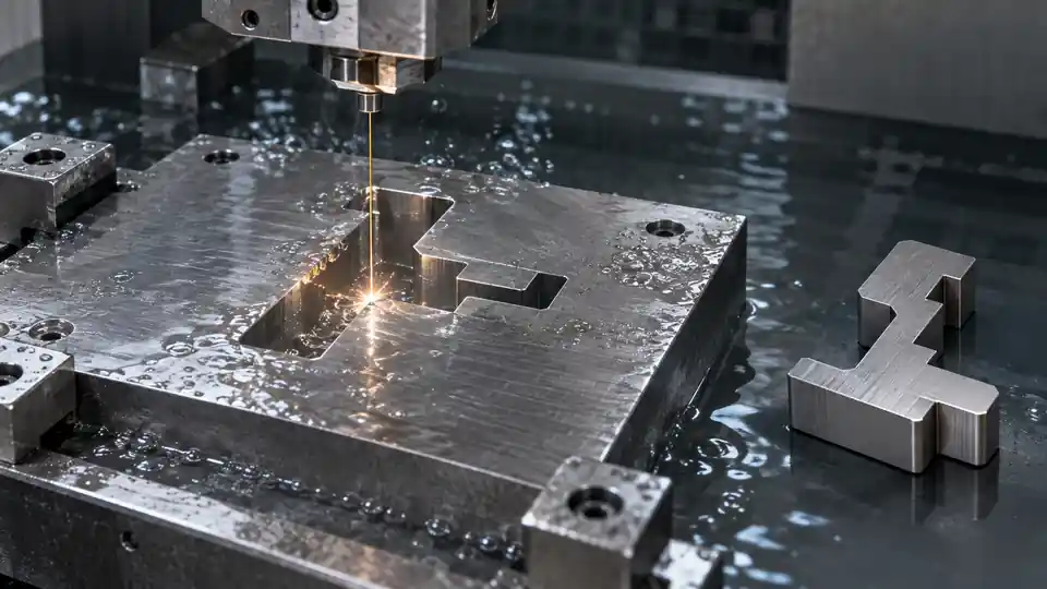
Wire EDM can produce narrow slots and small internal radii in electrically conductive materials without a rotating cutter entering the profile. It does not create a mathematically sharp inside corner. The minimum achievable radius depends on wire radius, discharge gap, path control, workpiece thickness, corner angle, wire behavior, and required accuracy and surface integrity.
This wire EDM sharp internal corner decision guide helps designers and buyers decide when wire cutting is appropriate, what geometry needs a start hole or open edge, how wire diameter and overcut set the corner floor, and when milling, sinker EDM, broaching, laser cutting, or a design change is better.
How Wire EDM Removes Material
A continuously moving wire electrode travels between upper and lower guides while controlled electrical discharges remove material across a dielectric gap. The wire does not mechanically cut like an end mill and ideally does not contact the workpiece.
The workpiece must be electrically conductive under the selected process. Hardened tool steel, stainless steel, titanium, nickel alloys, copper alloys, carbide, and many other conductive materials can be cut. Hardness usually has less effect on the removal mechanism than it does in conventional cutting, although material and condition influence settings, speed, integrity, and wire behavior.
The wire path is offset from the desired contour by the wire radius plus the effective spark gap and compensation. The final profile is produced through programmed motion, flushing, tension, power settings, and one or more passes.
Why an Internal Corner Still Has a Radius
The wire has finite diameter and a surrounding discharge gap. Even if the programmed centerline turns sharply, the material boundary cannot have a zero radius. A first estimate for the smallest theoretical internal radius is:
wire radius + effective spark gap
That estimate is not a guaranteed drawing value. Real corner form also depends on wire deflection/lag, thickness, flushing, energy, speed, machine control, material, skim strategy, and angular change. Shops need margin for stable processing and inspection.
Avoid specifying “sharp” without a number or functional definition. State the maximum internal radius or permitted corner-relief geometry and where it applies.
Wire Diameter and Overcut
Common production wire diameters vary by machine and application. Smaller wire enables smaller features and radii but can reduce cutting speed, increase break risk, require different guides/contact systems, and limit practical thickness.
Overcut is the radial compensation from the wire centerline to the finished surface. It accounts for wire radius and discharge gap. It changes with wire, material, power, pass, and machine technology. Do not calculate a released minimum radius from nominal wire diameter alone.
For quotation, give the allowed finished radius and ask the supplier to propose wire, offset, passes, and achievable tolerance for the actual thickness/material. If the corner sits at an angle or varies through height, include the complete 3D condition.
Corner Accuracy Is Not Only Corner Radius
A profile can have an acceptably small radius but inaccurate shape near the turn. As the path changes direction, the flexible wire can lag, bow, or be displaced by discharge and flushing forces. Inside corners may retain extra material; outside corners may overcut. Effects grow with aggressive roughing, height, poor flushing, and abrupt direction changes.
Modern controls adjust motion and process conditions around corners, but capability remains application-specific. Makino’s wire EDM tutorial explains wire bow/belly and how corner error can persist through workpiece thickness, especially when rough cutting is too fast. It also notes that skim passes and programmed corrections may be needed.
Inspect the entire wall and profile, not only the top opening. A vision system may show a good corner at one surface while mid-height bow exceeds profile tolerance.
Workpiece Thickness Changes the Decision
The wire is supported at guides above and below the workpiece. A taller cut increases the unsupported span and opportunity for deflection. Flushing becomes harder in variable-height, stepped, pocketed, or interrupted geometry.
Ask the supplier to evaluate:
- maximum and minimum cut height;
- abrupt thickness changes;
- openings that prevent sealed flushing;
- start and exit location;
- upper/lower guide access;
- required wall straightness and taper;
- corner shape through thickness; and
- whether slugs can move or trap the wire.
A radius demonstrated in a thin test coupon does not automatically apply to a tall production part.
Wire Access Determines Which Profiles Are Possible
Standard wire EDM needs the wire to pass through the workpiece between guides. An enclosed internal profile requires a start hole that connects the top and bottom surfaces. An open slot can be entered from an edge.
Blind pockets cannot be cut by ordinary wire EDM because the wire cannot pass through the bottom. Sinker EDM or milling is typically considered instead. Features obstructed by another flange or surface may also be inaccessible even if the local profile is through.
For every profile, show:
- whether it is through;
- start-hole diameter and allowed location;
- entry/exit path;
- guide clearance above and below;
- slug retention/removal plan; and
- surfaces that must not be cut.
Plan the Start Hole
The start hole must be large and straight enough for reliable threading under the chosen machine/wire/height conditions. It also needs to fit entirely within removable material unless the drawing permits witness.
Methods include drilling, EDM hole drilling, or machining from an existing opening. Hardened material, small diameter, high aspect ratio, and required location affect feasibility.
Do not place the start hole so close to a finished wall that positional error or hole taper breaks through. For a delicate slug, plan tabs, magnets, adhesive, clamps, or programmed stop so it does not drop and damage the part or wire.
Automatic rethreading can support multiple internal openings and unattended work, but interrupted/poor-flushing features need supplier confirmation.
Rough Cut and Skim Passes
The rough cut removes most material and establishes the basic profile. Skim cuts use lower-energy conditions and adjusted offsets to improve size, straightness, surface finish, and surface integrity.
More skims can improve results, but they add machine time and are not unlimited corrective magic. If the rough cut leaves excessive bow or distortion, the skim path can follow the existing error. The optimal number depends on tolerance, finish, material, height, and machine technology.
Ask for a pass plan tied to requirements, not a generic statement such as “three-pass EDM.” Identify whether the quoted tolerance and finish apply after every contour and corner.
Select Wire and Process Conditions as a System
Brass and coated wires, different tensile strengths, diameters, and core/coating designs support different combinations of speed, straightness, threading, finish, and difficult-material performance. The best option depends on the machine technology and workpiece. A wire promoted for fast roughing may not be the choice for a very small corner or fine final finish.
Wire tension must be high enough to support control but within the wire and machine limits. Excess tension can increase break risk; insufficient tension can worsen geometry. Conductivity, deionized-water condition, power, pulse strategy, feed, and flushing also interact. These are supplier process decisions unless a qualified customer requirement controls them.
Buyers should specify the finished result rather than mandate a consumable brand. Ask the supplier to record the process family when later repeatability or surface-integrity evidence depends on it. If a wire/process change is proposed after qualification, evaluate whether radius, offset, straightness, finish, recast, or cycle time must be reverified.
Control Distortion When the Slug Releases
Removing an internal slug changes the stiffness and residual-stress balance of both the part and slug. Thin frames, rings, hardened plates, and heavily machined blanks can move during or after release. Low cutting force does not mean zero distortion.
Plan the blank and sequence. Rough-machine symmetrically where possible, heat treat or stress relieve at the appropriate stage, establish references, and leave enough support around the profile. Tabs or programmed bridges can retain the slug until finishing, but their removal and blend location must be defined.
Measure the part in its required free or restrained state after stabilization and cleanup. A profile held flat in the EDM fixture may relax outside it. If flatness and contour are both critical, specify their relationship and avoid fixturing that masks warpage during inspection.
For a nest of parts or multiple openings, cutting order can redistribute stress. The supplier may rough all profiles, allow stabilization, and finish later, or use another balanced sequence. Validate the proposed route on representative material.
Fine Features and Micro-Wire Decisions
Very small wire expands the geometry range but narrows the process window. Start holes, guides, threading, flushing, wire breaks, machine resolution, environmental stability, and inspection all become more demanding. The finest advertised wire size does not establish a stable production feature.
Define minimum web thickness between adjacent cuts and from the profile to an external edge. Discharge removes material on both sides of the wire; a nominally thin web may overheat, distort, or break. Consider the sequence so released slugs do not damage neighboring features.
Micro corners also challenge inspection. Optical edge thresholds, focus, burr/recast, and calibration can be comparable to the tolerance. Agree the measurement plane, magnification, artifact/verification, and uncertainty. If sectioning is required, use a representative coupon or sacrificial part and define how it relates to production.
At very small scale, ask whether the functional interface truly needs a sharp vertex. A controlled relief, mating-part chamfer, or local clearance may provide a more inspectable and robust design.
Example: Hardened Insert With a Rectangular Opening
Consider a hardened tool-steel insert requiring a through rectangular opening with small corner radii and controlled profile. The example illustrates planning and is not a claim about a particular QuickCNCs production result.
The buyer supplies material condition, insert thickness, datum surfaces, maximum corner radius, profile tolerance, finish, and recast requirement. The supplier proposes an EDM-drilled start hole in the removable slug, a rough cut, and defined skim sequence. The slug is retained with tabs until the contour is stable.
Inspection measures the top and bottom profiles optically and checks representative mid-height straightness with an agreed method. Actual radius is reported at all four corners. A metallographic coupon made from the same material/process supports the surface-integrity decision when required.
If the first cut shows inside-corner stock and mid-height bow, simply adding a final skim may not be enough. The supplier revises roughing speed, corner strategy, flushing, and pass allowance, then repeats on an identified sample. Once accepted, wire/process family, program, fixture, and inspection method are controlled for repeat lots.
Surface Integrity and Recast Layer
EDM melts and vaporizes microscopic material regions. The finished surface can include a recast or white layer, heat-affected material, microcracks, altered residual stress, and embedded or transferred species depending on material and energy.
Skim passes generally reduce energy and can improve surface integrity. Critical fatigue, sealing, medical, aerospace, mold, or corrosion applications may require a maximum recast layer, metallographic verification, polishing, chemical removal, or a qualified process.
Specify the applicable material/process requirement and test method. “EDM finish” does not define surface integrity. Do not infer compliance from Ra alone; topography and metallurgical alteration are different attributes.
Surface Roughness and Appearance
Wire EDM creates a characteristic isotropic-looking cratered texture rather than cutter lay. Roughness improves through finishing passes. Required Ra/Rz and appearance influence cycle time.
State parameter, limit, units, standard/method, controlled surface, and measurement access. For small internal contours, confirm that a contact stylus can reach and traverse the surface. Replicas or noncontact methods may be considered under an approved plan.
If the surface will slide, seal, fatigue, coat, or be polished, define the functional condition after all downstream processing.
Taper and Four-Axis Cutting
Wire EDM can incline the wire by moving upper/lower guides independently, producing tapers and different top/bottom profiles within machine and fixture limits. Required angle, height, guide clearance, and profile relationship affect accuracy.
At a tapered internal corner, the effective geometry varies along height. Wire-guide interference, nozzle position, and compensation become important. Provide both profiles, datum relationships, angle tolerance, and inspection method.
Do not assume a small 2D radius can be maintained identically throughout a large taper. Ask for part-specific capability evidence.
Material and Heat-Treatment Sequence
Wire EDM is often performed after hardening because cutting force is low and hardness is not a conventional tool-wear barrier. This can avoid distortion from heat treatment after finishing.
The part must still be planned for residual stress, decarburization, scale, conductivity, and dimensional change. Rough machining before heat treatment may leave stock; stabilizing and grinding may establish reference surfaces; EDM then cuts critical profiles.
Some materials can crack or move when large slugs are released. Use stress-relieved stock, balanced roughing, tabs, staged cuts, and stabilization appropriate to the design. Validate with the supplier rather than adopting a universal sequence.
Fixturing and Datum Transfer
Wire EDM applies low mechanical force, but the part must be stable, located, conductive, and accessible. Fixturing should support without distorting thin sections and allow flushing and slug control.
Identify how drawing datums transfer to the EDM setup. Ground reference faces, dowel holes, or previously machined features may establish alignment. If the part must be removed and reinstalled, define requalification.
For multiple profiles, palletization can preserve relationships and reduce setup. Check that clamps and rails do not obstruct guide travel, tank motion, or taper.
Dimensional and Geometric Tolerances
Separate size, position, profile, straightness, parallelism, perpendicularity, taper, and surface finish. A machine’s advertised positional resolution is not part capability.
Capability depends on:
- workpiece size and height;
- temperature and thermal stability;
- material and condition;
- wire/guides/tension;
- rough and skim strategy;
- fixture and datum access;
- corner/contour dynamics;
- machine condition and calibration;
- operator/programmer practice; and
- measurement uncertainty.
Use a first article and actual results for demanding work. Define whether tolerances apply in free state and at what temperature.
Inspection of Sharp Internal Profiles
Inspect radius and form with a method that reaches the feature and resolves the tolerance. Options include optical measurement, vision systems, toolmaker’s microscope, CMM scanning/probing, contour equipment, replicas, or sectioned test coupons.
Consider line of sight, edge detection, burr/recast, lighting, focus, stylus radius, probe access, fitting algorithm, and measurement plane. A CMM touch probe may not enter the smallest corner. An optical top view may not reveal mid-height bow.
For critical through profiles, measure multiple heights or use a method that evaluates the wall. Record actual radius/profile rather than only pass/fail when the decision depends on process margin.
Design Alternatives to an Extremely Small Radius
Before requiring expensive EDM, ask what the mating geometry needs. Alternatives include:
- corner relief or dog-bone relief;
- mating-part chamfer or radius;
- split assembly;
- inserted wear plate;
- broached or shaped feature;
- sinker-EDM corner;
- drilled relief at the vertex;
- open-ended slot;
- localized clearance; or
- redesign that accepts an end-mill radius.
A relief can improve milling access and lower cost while maintaining assembly clearance. Check stress concentration, sealing, fatigue, flow, wear, and appearance before changing it.
Compare Manufacturing Routes
| Route | Best-fit condition | Corner/geometry limit | Main tradeoff |
|---|---|---|---|
| End milling | Open pockets, larger radii, 3D surfaces | Cutter radius and access | Fastest when radius is acceptable |
| Wire EDM | Through conductive profiles | Wire radius/gap and through access | Accurate intricate profiles, slower cycle |
| Sinker EDM | Blind pockets and local details | Electrode manufacture and wear | Reaches blind geometry, adds electrode cost |
| Broaching | Repeated straight-through profiles | Broach shape/access | High rate after dedicated tooling |
| Shaping/slotting | Certain internal keyways/profiles | Tool access and reciprocation | Useful for straight features, limited shape |
| Laser/waterjet | Sheet/plate profiles with broader tolerance | Kerf/taper/heat or stream effects | Fast rough profiles, finish machining may follow |
| Additive plus finishing | Complex internal architecture | Material/process qualification | Geometry freedom with different integrity |
| Design relief + milling | Function accepts relieved corner | Engineering approval | Often lowest total cost |
Cost Drivers
Wire EDM cost is driven by programmed cut length, height, material, removal area, number of passes, wire type/diameter, start holes, threading reliability, flushing, corner control, taper, tolerance, surface finish, inspection, setup, and slug handling.
Many repeated small openings add start-hole and threading time. Extremely fine wire reduces removal rate and increases fragility. Tight surface finish or straightness adds skims. A large slug may need planned retention and manual intervention.
Ask quotes to separate nonrecurring programming/fixture/start-hole preparation from recurring EDM time, inspection, and finishing. Quantity can justify multi-part setups or a broach/alternative process.
Supplier Feasibility Questions
- What wire diameter and effective corner radius are proposed?
- What finished radius/tolerance can be held through the stated height?
- How many rough/skim passes support size, form, and finish?
- Where is the start hole and how is threading verified?
- How will flushing work at variable thickness or openings?
- How is slug movement prevented?
- What recast/surface-integrity condition is expected and verified?
- How are datums transferred and the part restrained?
- What inspection method reaches the corner at multiple heights?
- What design relief would reduce risk or cost?
Request evidence from comparable material, height, radius, and tolerance—not only a generic machine datasheet.
Common Failure Modes
The drawing calls for a perfectly sharp corner
No maximum radius or relief is given. Manufacturing and inspection cannot agree. Define a numeric or functional acceptance.
Radius is calculated from wire diameter only
Spark gap and process margin are omitted. Use supplier-supported finished capability.
Top-view inspection misses wall error
Wire bow creates shape change through thickness. Inspect representative heights or the full profile.
A rough cut is pushed too fast
Corner error and belly remain and skims cannot fully correct them. Balance rough accuracy with finishing plan.
Wire EDM is specified for a blind pocket
The wire cannot pass through. Use sinker EDM, milling, split construction, or redesign.
Surface roughness is treated as recast control
A low Ra does not alone prove metallurgical integrity. Specify and verify the relevant requirement.
RFQ Checklist
Provide:
- controlled 3D model and 2D drawing;
- material, condition, and thickness range;
- through/blind condition and guide clearance;
- maximum internal radius or permitted relief;
- profile, size, position, straightness, taper, and finish tolerances;
- start-hole location/size restrictions;
- surfaces protected from wire entry/exit marks;
- recast or surface-integrity requirements;
- heat-treatment and finishing sequence;
- lot quantity and repeat forecast;
- inspection method/report expectations; and
- functional reason for the sharp profile.
Ask the supplier to return proposed wire, passes, corner result, assumptions, inspection approach, and alternatives.
Choose Wire EDM When the Geometry and Evidence Fit
Wire EDM is often the best route for conductive through profiles that need smaller internal radii than practical rotary cutters, especially in hardened or difficult materials. Its limits are physical and measurable: wire diameter, discharge gap, access, height, deflection, flushing, surface integrity, and inspection.
For a QuickCNCs RFQ, send the controlled model/drawing, material and thickness, maximum allowed radius, start-hole/access constraints, surface-integrity requirement, and actual-value inspection needs. We can assess milling, wire EDM, sinker EDM, or a combined route and identify where a small design relief would improve cost or robustness.
Compare the access assumptions with EDM and wire EDM services and the acceptance method on CNC tolerances and inspection. Submit the maximum corner radius and entry restrictions through Request a Quote.