
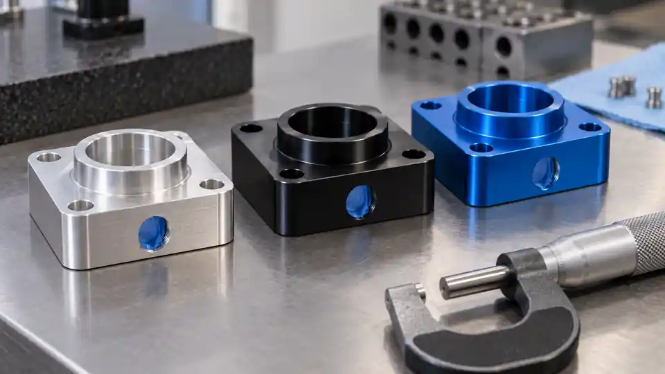
Type II sulfuric-acid anodizing can improve corrosion resistance and provide clear or dyed appearance on aluminum CNC parts. It also changes the surface. Some of the oxide forms above the original metal surface and some develops inward, while cleaning and etching before anodizing can remove material. The net dimensional result depends on alloy, pretreatment, coating thickness, masking, geometry, and process control.
This Type II anodize CNC dimension decision guide explains how to specify the finish, budget size change, control fits and threads, set realistic color criteria, and inspect the final part. Do not use a universal “half in, half out” rule as a drawing tolerance. Obtain the anodizer’s process capability and use the governing specification and customer requirements.
Define Type II and Class Correctly
Under MIL-PRF-8625 terminology, Type II is conventional sulfuric-acid anodizing. Class 1 is non-dyed; Class 2 is dyed. Those designations do not by themselves define every thickness, color, seal, appearance, or dimensional requirement.
The official DLA MIL-PRF-8625 document record identifies the current active performance specification and states that it covers six types and two classes of anodic coatings for non-architectural aluminum applications. Always check the live revision required by the purchase order.
If another standard or proprietary customer specification controls, use its terminology. Do not mix “Type II,” “architectural Class II,” and a supplier’s marketing name as though they were equivalent.
A Complete Finish Callout
A useful drawing or PO callout identifies:
- governing specification and revision;
- anodize type and class;
- required coating thickness or range when applicable;
- alloy and temper;
- clear or exact color requirement;
- seal and any restrictions;
- pretreatment or appearance requirement;
- surfaces to coat and mask;
- rack/contact mark locations;
- post-finish dimensional requirements;
- corrosion, adhesion, color, gloss, or other tests;
- cosmetic zones and boundary samples; and
- certificate and lot-traceability needs.
“Black anodize” is not enough. Two processors can legitimately choose different coating thickness, etch, dye, seal, and rack approach and return visibly or dimensionally different parts.
How Anodizing Changes a Surface
Anodizing converts aluminum at the surface into anodic oxide; it is not simply a layer painted on top. Growth above the original surface affects external sizes and reduces openings. Penetration below the original surface affects the metal/oxide interface. Pretreatment may remove material before oxide growth.
Therefore, the final change from machined size is:
pretreatment removal + anodic growth + any post-process change
Each term varies. The ratio of outward growth to total oxide thickness is not a fixed drawing constant for every alloy/process. Measure or qualify the actual supplier route when fit is critical.
Thickness, Growth, and Dimension Are Different Numbers
Coating thickness measures the anodic oxide. Outward growth is the portion that increases an external surface relative to its pre-anodize location. Dimensional change compares the finished feature with the machined feature and also includes etching or other preparation.
For an external diameter, coating grows on both opposite surfaces. For a hole, growth on opposing walls reduces diameter. For a single planar surface, growth changes its location and can affect a datum or step.
Do not subtract the nominal coating thickness from a bore and assume the result. Request the anodizer’s expected pre/post change and tolerance for the alloy, thickness, pretreatment, and feature.
Build a Tolerance Budget
Start with the functional final-state limit. Then allocate variation among machining, cleaning/etch, anodic coating, masking transition, measurement, and any post-anodize operation.
| Contributor | What changes | Evidence needed |
|---|---|---|
| Machining | Pre-finish size, form, location | Actual pre-anodize data and process capability |
| Pretreatment | Removes material; can be uneven | Processor route and representative measurements |
| Coating thickness | Adds oxide with local variation | Specification, lot data, thickness method |
| Outward growth | Alters external and internal sizes | Qualified pre/post correlation |
| Masking | Creates uncoated zone and transition | Drawing boundary and sample approval |
| Racking | Leaves contact marks, may affect local coverage | Approved rack zones |
| Sealing/dyeing | Affects appearance and possibly measurements | Final-condition inspection method |
| Metrology | Different methods/locations produce variation | Correlation and uncertainty |
If the total expected variation consumes the tolerance, redesign or choose a controlled post-finish operation. Do not expect the machine shop or anodizer to compensate an impossible stack silently.
Pre-Anodize Versus Post-Anodize Dimensions
Every critical feature needs an acceptance state. Three common approaches are:
- Machine to a controlled pre-anodize size and accept coating to its own requirement.
- Require the final post-anodize dimension, leaving the supplier to develop a validated allowance.
- Mask or finish-machine/ream/lap/grind the feature after anodizing.
Final-state dimensions protect function but may require process development and pre/post records. Pre-finish dimensions are easier to measure but do not prove final fit. Post-machining removes coating and may expose bare aluminum, requiring corrosion or electrical design review.
Mark the state clearly on the drawing and inspection report. Do not pool measurements from before and after finish.
Bores, Shafts, and Bearing Fits
Anodize can reduce bore diameter and increase shaft or boss diameter. Thickness nonuniformity, current distribution, solution flow, pretreatment, and racking affect local result. Small/deep holes and recessed features may not coat like open external faces.
For a bearing or dowel interface, decide whether the surface should be anodized. Options include:
- mask the fit;
- machine allowance and anodize to final size;
- hardcoat or another finish designed for wear;
- size after anodize and protect exposed aluminum; or
- redesign the interface with an insert.
Consider installation stress, coating brittleness, chipping at edges, galvanic contact, and service removal. Verify with representative assembly and actual-value inspection.
Threads
Anodize affects internal and external thread flanks and pitch diameters. Coating buildup can interfere with assembly, while masking leaves an unprotected surface. Small threads are particularly sensitive.
Define whether threads are masked, anodized, chased after finish, or fitted with inserts. If chased, determine how exposed aluminum is protected and how debris is controlled. Do not rely on forcing a screw through coating.
Use functional thread gaging in the final state when appropriate, but recognize that a pass/fail gage does not quantify coating condition. For torque-critical joints, validate fastener material, lubricant, finish, preload, and repeated assembly.
Datum Surfaces and Geometric Tolerances
Coating on a datum can change contact and measured relationships. Masking a datum may preserve metal reference but create a step at the transition. If a CMM alignment uses coated faces, coating variation becomes part of the result.
State whether datums and geometric tolerances apply after anodize. Select accessible, stable reference surfaces. For flatness and profile, avoid soft fixturing that hides warpage. Thin parts may distort during pretreatment or racking.
If a functional mount requires metal-to-metal contact, define masking, surface finish, corrosion protection, and allowable step around the pad.
Masking Design
Show masking boundaries as controlled geometry. “Mask all critical surfaces” makes the anodizer interpret design intent. Dimension boundaries from datums and identify holes, threads, lands, contacts, and rack zones.
Masking has practical tolerances. Tapes, plugs, lacquers, fixtures, and reusable masks produce different edge definition and cost. Complex internal masks may leak or trap chemistry.
Allow a transition zone where function permits. Keep critical sealing edges and visual boundaries away from irregular mask transitions. Review plug insertion/removal for small holes and delicate threads.
Color Is a System Result
Dyed Type II color depends on alloy, temper, lot, product form, surface preparation, coating thickness, dye bath, seal, geometry, viewing light, and time. Black can show undertone or gloss differences. Clear anodize can still change appearance.
Define color with an approved physical master and acceptable boundary samples where appearance matters. Use instrument values only with a complete color space, illuminant, observer, geometry, surface condition, sampling locations, and tolerance.
Do not approve a supplier from a photograph alone. Camera exposure, white balance, compression, background, and display calibration change the image.
Alloy and Lot Effects on Appearance
6061, 7075, 2024, cast alloys, welds, and fillers can anodize differently. Silicon, copper, grain structure, product form, heat treatment, and surface history affect color and uniformity.
Parts assembled from different alloys may not color-match even in the same batch. Welded areas can show contrast. Different raw-material heats can create shade shifts.
If matching is important, keep alloy/form/lot and pretreatment controlled, process parts together when practical, and approve representative samples. State whether exact match to another material is realistic.
Mechanical Pretreatment and Texture
Machining, sanding, polishing, brushing, blasting, and chemical etching establish the substrate appearance seen through or under anodize. Anodizing does not hide deep scratches, chatter, pits, blend lines, or stock defects.
Define direction, roughness or visual master, media, pressure, and allowed edge rounding where needed. Blasting can create uniform matte appearance but changes dimensions, texture, and corner definition. Polishing adds manual variability.
Protect cosmetic surfaces before and after processing. Rack, rinse, handling, and packaging marks can occur late.
Chemical Cleaning and Etch Allowance
The anodize line normally cleans and deoxidizes the aluminum; an alkaline etch may be used to create a matte appearance or remove surface condition. These steps can remove metal before oxide growth and can attack different alloys, tempers, welds, and machined features at different rates.
If dimensional control is tight, identify whether a caustic etch, bright dip, deoxidizer, or other pretreatment is permitted. “Standard prep” may vary between processors. Deep etching can soften edges, enlarge holes, reduce bosses, reveal grain, and change the net pre/post dimension.
Use representative coupons or first articles to correlate the complete route, not anodizing alone. A pre-anodize measurement followed by a post-anodize measurement captures net effect only when the same feature, temperature, and method are used. Record pretreatment with the lot.
For a cosmetic matte finish, approve the texture and color together. Changing blast media or etch time to correct appearance can also change dimension. Require engineering review before process adjustments move outside the qualified window.
Racking, Current Distribution, and Geometry
Electrical contact is necessary during anodizing, so rack marks cannot be eliminated everywhere. Place them on nonfunctional, hidden, or later-machined zones and show acceptable size/location. The contact must carry current without burning the part or losing connection.
Part geometry affects current density and solution exchange. Edges and projections can behave differently from recessed surfaces, deep holes, blind pockets, closely spaced parts, and interior corners. A flat witness panel does not reproduce every local condition.
Review racking orientation for trapped air and chemistry, drainage, staining, and contact. Add drain/vent access where practical. Large thin parts may deform under their own weight or rack force; establish support and free-state inspection.
During qualification, map coating thickness at functional external faces, bores, recesses, and locations expected to be high or low. Use that evidence to place tolerances and mask boundaries rather than assuming perfect uniformity.
Select the Standard and Acceptance Set
Different specifications control different products and properties. Use one coherent system unless the drawing clearly reconciles several.
| Requirement choice | What it should establish | Avoid |
|---|---|---|
| MIL-PRF-8625 Type II/Class | Non-architectural performance framework and class | Calling a color without thickness/test choices |
| ISO 7599 | Decorative/protective anodize specification method | Assuming it duplicates a military callout |
| Proprietary customer spec | Program-specific process and acceptance | Referencing it without supplying controlled access |
| Coating thickness standard | Instrument/method and limitations | Mixing values from different locations/methods |
| Color/gloss standard | Viewing or instrument geometry | A numerical color tolerance with no master or setup |
| Corrosion/adhesion test | Lot/sample/acceptance conditions | Generic “salt spray pass” without the governing procedure |
When requirements conflict, obtain written clarification. A supplier should not choose the easiest clause from each document. Record the standard editions effective for the order and any approved deviation.
Example: Anodized Bearing Housing
Consider a 6061 housing with two bearing bores, a flat mounting datum, black external appearance, threaded cover holes, and masked grounding pads. The example shows a planning method and is not an actual customer result.
Engineering first defines which surfaces need corrosion/color and which need bare metal. Bearing bores are machined with a qualified pre-anodize allowance and coated to final size; grounding pads are masked with dimensioned boundaries; threaded holes receive an approved masking strategy. The primary mounting datum remains coated, so final flatness is inspected after anodize.
The supplier measures selected bores and bosses before and after a representative first lot. The anodizer records alloy/lot, pretreatment, coating thickness at agreed locations, dye/seal, rack orientation, and contact locations. Appearance is compared with a physical master under controlled light.
If final bores trend small, the team does not simply enlarge the pre-anodize offset from one part. It checks measurement correlation, etch removal, coating distribution, lot variation, and assembly fit, then approves a controlled allowance. Repeated lots retain pre/post samples until capability is demonstrated.
Packaging and Handling After Anodize
Fresh finished surfaces can be scratched, stained, or marked during rinsing, inspection, assembly, and transport. Define handling gloves, clean separators, caps for critical openings, approved bag/foam materials, and pack quantity. Avoid adhesive or paper contact that transfers residue or moisture.
Protect threads, seal lands, cosmetic faces, and masked electrical pads without creating abrasion. If protective oil or film is allowed, confirm compatibility with assembly, bonding, vacuum, or cleanliness requirements.
Receiving inspection should examine damage before parts are stacked or assembled. Record the lot and packaging condition so a transport issue is not misdiagnosed as an anodize-process failure.
Sealing and Functional Tradeoffs
Sealing closes pores to improve corrosion behavior and dye stability, depending on the specified system. Seal type can affect color, surface, electrical behavior, and later bonding or painting.
Do not omit or change sealing for appearance without engineering approval. If the part will be adhesively bonded, painted, conduct electricity, or operate in a sensitive environment, confirm compatible pretreatment and seal.
Specify tests required by the governing finish document and application. A certificate statement alone may not replace required lot testing.
Electrical Contact and Grounding
Anodic oxide is electrically insulating. Ground pads, bonding surfaces, connector shells, EMI gasket lands, and threaded returns need deliberate treatment.
Mask conductive zones or use an approved conductive conversion coating where appropriate. Define boundary, contact resistance, corrosion protection, cleanliness, and test. Fastener teeth that randomly break through coating are not a controlled electrical design.
Consider galvanic couples at exposed aluminum/stainless-steel contacts. Keep electrolyte out through sealing, drainage, isolation, or other design controls.
Surface Finish, Friction, and Wear
Type II anodize can protect and color surfaces but is not equivalent to Type III hardcoat. Sliding, bearing, repeated assembly, or abrasive contact may require a different finish or insert.
Coating changes roughness and friction; a measured pre-anodize Ra does not guarantee post-anodize performance. Specify final-state texture when it matters and confirm accessible measurement.
At sealing lands, control scratches, pits, mask edges, and local buildup in addition to average roughness. Conduct a representative leak or functional test where appropriate.
Edge Breaks and Corner Behavior
Sharp edges can produce thin or fragile coating, electrical concentration, burning, or chipping. Heavy edge breaks alter fit and appearance. Specify practical radii or chamfers based on function.
Avoid zero-radius internal transitions that trap chemistry or are hard to rinse. Add drain/vent features to blind cavities where design permits. Coordinate with the anodizer early for deep pockets, small holes, threaded cavities, and welded assemblies.
Coating Thickness Measurement
Select a method appropriate to substrate, thickness, geometry, color, and accessibility. Eddy-current methods are common on aluminum but require calibration and suitable locations. Cross-section microscopy is destructive. Some optical methods have surface/color limitations.
ISO 2128:2010 covers a split-beam microscope method and notes limitations for opaque/dark or uneven surfaces. Other standards and methods may control your program. Name the method and sampling plan.
Measure representative functional surfaces, not only the easiest flat coupon. If a witness coupon is allowed, define how it represents rack position, current density, alloy, preparation, and geometry.
Color and Gloss Inspection
Use controlled lighting, viewing distance/angle, background, and sample orientation. Specify whether the decision is visual, instrumental, or both. Distinguish color from gloss and texture.
ISO 7668:2021 addresses specular reflectance and gloss measurement for anodized aluminum at defined geometries. It notes applicability conditions, including comparison among similar colors. Use the required standard rather than a generic glossmeter setting.
For decorative/protective anodizing, ISO 7599:2018 identifies characteristic properties, test methods, performance requirements, alloy suitability, and pretreatment importance. Check whether it or another specification is contractually applicable.
Lot Control and Sampling
Define an anodize lot in the quality plan. Record processor, date/bath lot as required, alloy, part lot, rack/load, pretreatment, dye, seal, and test coupons. Keep finished parts traceable to the machining and material lots.
Sampling should reflect risk, specification, quantity, geometry, and process stability. Thickness at one external face may not protect small bores. Color approval may require several parts across rack locations.
When a lot fails, contain all associated pieces and evaluate rework/strip-and-reanodize. Stripping removes material and can change dimensions and surface. Do not reprocess without approved limits and updated inspection.
Dimensional Inspection Sequence
A robust route may include:
- inspect critical pre-anodize dimensions;
- identify and protect the part/lot;
- verify masking/rack instructions;
- anodize, dye, and seal;
- clean and stabilize;
- inspect coating and appearance;
- measure final critical dimensions/geometric tolerances;
- check threads, fits, contacts, and functional tests; and
- release certificates and actual results.
Compare pre/post data during qualification to establish allowance. Continue risk-based monitoring; do not assume correlation remains constant after alloy, processor, thickness, pretreatment, or geometry changes.
Common Drawing and RFQ Errors
Only “black anodize” is stated
Type, class, thickness, seal, standard, color, and masking are ambiguous. Complete the callout.
Full coating thickness is used as outward growth
Penetration and pretreatment are ignored. Use process-specific pre/post evidence.
Every hole is made undersize by the same allowance
Feature geometry and local coating vary. Identify critical final sizes and validate.
Color is approved by email photo
Viewing conditions are uncontrolled. Use a physical master/boundary samples or defined instrument method.
Masking boundaries are described verbally
The transition enters a fit or cosmetic zone. Dimension the mask on the drawing.
Threads are chased without corrosion review
Bare aluminum is exposed. Approve the final surface strategy.
Re-anodize is treated as harmless
Stripping removes material and affects dimensions. Require engineering disposition and reinspection.
RFQ Checklist
Send:
- controlled model/drawing;
- alloy, temper, product form, and certification;
- anodize specification/revision, Type II, class, thickness;
- color, gloss, texture, and approved samples;
- pretreatment and seal;
- masked/coated/rack-mark zones;
- pre- and post-anodize dimensional states;
- tight bores, bosses, threads, datums, and contacts;
- corrosion/adhesion/color/thickness tests;
- lot definition, sampling, and certificates;
- quantity and repeat cadence; and
- rules for rework or stripping.
Ask the machine shop and anodizer to return a coordinated allowance, masking method, expected variation, inspection sequence, and exceptions.
Treat Anodize as Part of the Dimensional Design
Type II anodizing is both a surface process and a dimensional input. Successful parts start with a complete callout, a realistic pre/post tolerance budget, intentional masking, alloy-aware color criteria, and inspection in the final state.
For a QuickCNCs anodized-part RFQ, send the model/drawing, alloy/temper, finish standard and thickness, critical final dimensions, mask/rack zones, cosmetic master, electrical contacts, and required records. We can coordinate machining allowances and inspection with the proposed finishing route while leaving product and appearance approval with the authorized buyer.
Align the coating callout with the available surface finishing route and define final-state measurement on CNC tolerances and inspection. Submit the masking map, thickness range, and post-anodize dimensions through Request a Quote.