
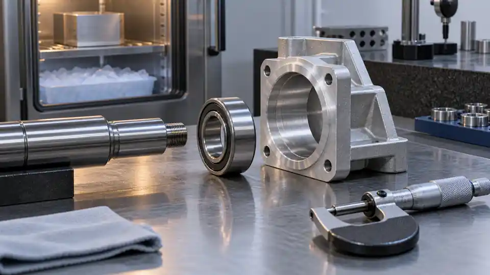
A press fit joins a shaft, pin, bushing, bearing, or insert to a bore by making the mating features overlap dimensionally before assembly. The shaft or outside diameter is larger than the hole, so installation creates contact pressure. That pressure can transmit load and prevent movement, but too much interference can split a hub, collapse a bearing race, distort a thin housing, gall the surfaces, or make assembly impossible. Too little can disappear at operating temperature and allow slip or fretting.
The correct tolerance is not selected from a chart by nominal diameter alone. It depends on material pair, hub geometry, surface texture, edge condition, temperature, loading, required retention, assembly method, coating, and the variation of both mating parts.
This press fit bore CNC tolerance decision guide explains the design and quotation inputs. It does not prescribe a universal allowance. Use an appropriate engineering analysis and the controlled edition of the applicable fit standard. ASME B4.1 addresses preferred limits and fits for cylindrical parts, while ISO 286-1 defines the ISO code system and basic hole/basic shaft concepts. Confirm which system governs the drawing.
Define Interference at Both Limits
For a simple cylindrical pair:
Diametral interference = actual shaft or insert OD − actual bore ID.
The assembly must work across the full tolerance combination:
Minimum interference = minimum shaft OD − maximum bore ID.
Maximum interference = maximum shaft OD − minimum bore ID.
If the first result is negative, the worst-case combination has clearance. If the second is too large for material, geometry, or assembly, the worst-case combination can fail even when both individual parts pass inspection.
Always state whether a value is diametral or radial. Radial interference is one-half the diametral difference for a round pair. Mixing the two can double or halve the intended allowance.
Tolerance is not the same as allowance
Allowance describes the intentional difference at a material-limit condition in a fit system. Tolerance describes permitted size variation. The functional window is created by both mating size ranges, not by one nominal interference value.
Show the upper and lower limits on the drawing or use a controlled fit designation. If a fit code is used, include the standard and revision. Do not combine an ISO fit code with an unrelated plus/minus size that changes the result.
Hole-Basis and Shaft-Basis Systems
In a hole-basis system, the hole tolerance position is standardized and the shaft is selected to create clearance, transition, or interference. This is common because standard drills, reamers, boring tools, and gages make holes convenient to standardize.
In a shaft-basis system, the shaft tolerance is standardized and the hole varies. It can be useful when commercial shafting, bearings, pins, or a common shaft size is the fixed input.
The design should choose a basis from the complete assembly. A machine shop making only the housing cannot finalize the fit without the mating OD and its actual specification. Supply the bearing or insert drawing, controlled interface limits, and service condition.
Start with the Required Function
Press fits serve different functions:
- retaining a bearing ring without creep;
- locating a dowel or insert;
- transmitting torque or axial load;
- sealing a plug or sleeve;
- creating electrical or thermal contact;
- supporting a wear bushing;
- holding an assembly before another retention method is applied.
Define the load magnitude, direction, cycles, shock, vibration, temperature range, environment, and permitted movement. For a bearing, follow the bearing manufacturer’s fit guidance and account for which ring rotates relative to load, housing/shaft material, wall thickness, and internal clearance. Do not use a generic press-fit table as a substitute.
If the fit is only for location and a fastener carries the load, a lighter interference or transition fit may be adequate. If the fit must transmit torque alone, the design needs a validated contact-pressure and friction basis with appropriate safety factors.
Material Pair and Hoop Stress
Interference creates pressure at the interface. The hub expands and the inserted member may compress. Stress depends on elastic modulus, Poisson’s ratio, diameters, wall thickness, length, geometry, and boundary conditions. A thin aluminum boss around a steel pin responds differently from a thick steel hub around a steel shaft.
Do not select maximum interference without checking:
- hub hoop and radial stress;
- shaft or insert compression;
- local yielding and permanent bore growth;
- stress concentration at steps, slots, threads, and thin walls;
- brittle cracking risk in cast, hardened, ceramic, or plastic materials;
- bearing-race deformation and loss of internal clearance;
- fatigue under cyclic pressure and service loads;
- creep or stress relaxation at temperature.
Closed-form thick-cylinder equations can screen simple geometry. Finite-element analysis or test may be justified for nonuniform hubs, split clamps, thin walls, high temperature, brittle materials, or critical consequences. State assumptions and do not apply a calculation beyond its geometry.
Edge distance and local wall thickness
The average outside diameter of a hub can hide a local weak section. Cross holes, pockets, flats, keyways, threads, and nearby edges reduce stiffness and concentrate stress. Review the minimum ligament around the full circumference and along the engagement length.
A press-fit bore near a thin edge may ovalize even if a nominal thick-cylinder calculation looks acceptable. CNC workholding can also distort the bore during machining, causing it to change size after unclamping.
Temperature Can Reverse the Fit Decision
Materials expand at different rates. For a diameter (D), a first-order free thermal change is:
ΔD = α × D × ΔT, where α is the coefficient of thermal expansion.
Use consistent units and appropriate material data over the temperature range. The operating interference changes by the difference between the bore’s and shaft’s thermal growth, modified by assembly constraints and gradients.
An aluminum housing around a steel insert generally expands more with increasing temperature, which can reduce interference. At low temperature, interference may increase. A polymer housing may have much larger thermal expansion and time-dependent relaxation. Local heating from a bearing or motor can produce a gradient rather than uniform temperature.
Check at least:
- minimum assembly temperature;
- maximum assembly temperature if thermal installation is used;
- minimum and maximum service temperature;
- transient thermal gradients;
- storage and transport extremes when relevant;
- measurement reference temperature.
Minimum interference must still satisfy retention at the service condition, while maximum interference must remain safe at the worst assembly and operating condition.
Surface Texture and Contact Behavior
Surface texture affects installation force, asperity flattening, lubrication retention, fretting, and final contact. A very rough surface can require high initial force while losing effective interference as peaks deform. A very smooth pair may increase galling or reduce lubricant retention for certain materials.
Specify the texture parameter, limit, surface, and measurement method appropriate to the function. Do not assume a general finish note produces a suitable bearing seat. Consider waviness, lobing, cylindricity, taper, and straightness in addition to Ra.
The bore and shaft can both meet two-point size while having form error that changes local contact. For a long fit, taper can concentrate load at one end. For a thin ring, clamping and measurement can hide out-of-roundness.
Coatings and plating
Anodize, hardcoat, plating, conversion coating, paint, solid-film lubricant, or thermal spray can change dimensions and friction. Define whether fit sizes apply before or after finish. Identify masked surfaces, coating thickness, buildup, and whether the finish can withstand pressing.
Do not treat coating as bulk material with a simple nominal subtraction unless the process and thickness distribution are controlled. A brittle or poorly supported coating can crack, flake, or scrape during insertion.
Lead-In, Edge Break, and Engagement Length
A chamfer or lead-in aligns the parts and reduces edge shaving. Define it on both components as needed. A sharp shaft edge can broach the bore; an excessive chamfer reduces effective engagement length and contact area.
Engagement length influences retention and force. The usable contact length may be shorter than the nominal hub thickness because of chamfers, reliefs, grooves, or bore taper. Define the functional length in the analysis.
Avoid a shoulder or fillet conflict that prevents full seating. Provide relief where a shaft corner radius meets a bore edge. State the seating face and final axial position; press force alone is not a reliable position control.
Estimate Assembly Force Carefully
Press force depends on contact pressure, interface area, friction, lubrication, surface texture, alignment, elastic/plastic response, and insertion speed. A simplified relationship may treat axial force as interface pressure multiplied by cylindrical contact area and an effective friction coefficient. The coefficient is highly variable, and real force can include edge deformation and misalignment.
Use calculations to size equipment and screen risk, then validate the actual material, finish, geometry, lubricant, and speed when consequences matter. Define:
- maximum permitted assembly force;
- force versus displacement monitoring if required;
- insertion speed and alignment method;
- lubricant type and cleanliness compatibility;
- support beneath the receiving part;
- stop position or shoulder contact;
- rejection criteria for force signature.
A high force can distort the part before the fit is seated. Supporting the housing on an inappropriate surface can damage a flange or transfer load through a bearing.
Thermal and Assisted Assembly
Heating the hub, cooling the insert, or both can create temporary clearance and reduce press force. This is often called a shrink fit even when final retention is by interference.
Plan the process:
- calculate the required assembly clearance at controlled temperatures;
- set maximum/minimum temperatures compatible with material, heat treatment, coating, lubricant, and components;
- control soak time and verify actual temperature;
- define handling, alignment, and available assembly time;
- provide a positive seating feature;
- allow stabilization before final inspection or loading;
- address condensation, cleanliness, oxidation, and operator safety.
Do not use uncontrolled flame heating or an unspecified freezer method for a qualified assembly. A thermal method can reduce force but does not repair an unsafe final interference.
CNC Processes for Press-Fit Bores
Boring
Single-point boring can control size and geometry while correcting location from a machined datum. Tool stiffness, insert geometry, material, thermal stability, and final-pass strategy matter. In-process probing may support setup but final acceptance requires a suitable measurement method.
Reaming
Reaming is efficient for repeat bores when pre-hole size, alignment, material, tool condition, and chip control are stable. It tends to follow the existing hole and is not the best method for correcting significant position error. Tool wear and built-up edge can shift size.
Circular interpolation
Milling a bore by interpolation offers diameter adjustment and can machine several sizes with one tool. Form and size depend on machine motion, tool deflection, path, runout, and calibration. It can be effective for many housings but must be validated for the required fit.
Honing, jig grinding, and cylindrical grinding
Honing can improve bore size, cylindricity, and texture when adequate stock and access exist. Jig grinding can achieve precise size and location in hard materials. Shaft OD may be finished by cylindrical grinding. These processes add setup, allowance, inspection, and lead time, so reserve them for justified requirements.
Line boring or matched assembly
Long coaxial bores may require line boring or another common-axis method. Matched machining can solve a unique assembly but may destroy interchangeability. If replacement parts must fit universally, do not accept undocumented match-marking as the production solution.
Inspection Strategy
Size alone is not enough. Define the final condition and measure:
- bore and shaft size across the required length;
- roundness/cylindricity/taper where function requires;
- position, perpendicularity, or runout to assembly datums;
- surface texture on the functional zone;
- coating thickness or masking state;
- temperature at measurement;
- actual mating-part lot or controlled master when functional verification is used.
Air gaging can provide sensitive comparative bore measurement in production but needs masters and controlled conditions. Bore gages and micrometers provide direct shop measurements with method limitations. CMM measurement can relate the bore to datums but point strategy and form evaluation matter. Fixed limit gages may be efficient for size boundaries.
The QuickCNCs quality assurance page describes available equipment. The inspection plan should name the characteristic, datum, method, unit, sampling, actual-value requirement, and acceptance limit.
Worst-Case Fit Table
Build this table with actual design values:
| Condition | Shaft/insert OD | Bore ID | Resulting interference | Required decision |
|---|---|---|---|---|
| Minimum at reference temperature | shaft minimum | bore maximum | minimum OD − maximum ID | enough retention? |
| Maximum at reference temperature | shaft maximum | bore minimum | maximum OD − minimum ID | safe stress and assembly force? |
| Hot service | thermally adjusted OD | thermally adjusted ID | hot OD − hot ID | slip, creep, or fretting risk? |
| Cold service | thermally adjusted OD | thermally adjusted ID | cold OD − cold ID | excess stress or race collapse? |
| Coated final condition | finished OD | finished ID | final OD − final ID | buildup and surface integrity acceptable? |
Do not enter only nominal values. Use tolerance limits, material data, and final process condition.
Alternatives to a Press Fit
If the interference window is too narrow or assembly risk is high, consider:
- transition or slip fit with a shoulder and fastener;
- retaining compound with controlled gap, cleanliness, cure, and service compatibility;
- split clamp or clamping collar;
- key, spline, flat, or pin for torque transfer;
- threaded retention, locknut, or end plate;
- snap ring or mechanical retainer;
- thermal shrink fit with controlled process;
- tapered fit or draw-in joint;
- flange and bolted interface;
- one round dowel plus one relieved locator for position.
Each alternative changes load path, tolerance, serviceability, sealing, fatigue, corrosion, cleanliness, and inspection. Do not select it solely because machining becomes easier.
Common Failure Modes
Fit becomes loose at operating temperature
The material pair expands differently or the hub creeps. Recalculate the full temperature range and time-dependent behavior.
Housing cracks or permanently grows
Maximum interference, local wall thickness, brittle material, or edge stress is unsafe. Review stress, geometry, and assembly support.
Bearing runs hot after installation
The fit may reduce internal clearance or distort the race. Follow bearing-specific guidance and verify installed geometry and operating conditions.
Parts gall or seize during pressing
Misalignment, surface condition, material compatibility, insufficient lead-in, contamination, or lubrication is unsuitable. Control the assembly process rather than simply increasing press capacity.
Insert backs out or rotates
Minimum interference, engagement length, temperature, cyclic load, or surface condition is inadequate. Evaluate a different fit or secondary retention.
Bore measures differently after unclamping
Machining fixture force distorted a thin housing. Measure in the specified free or assembly state and improve workholding/process sequence.
Plan a Fit Validation Build
For a new material pair, thin housing, bearing seat, thermal environment, or high-consequence joint, validate the fit before releasing full production. Use parts that represent production material, condition, surface finish, coating, geometry, and machining process. A smooth laboratory ring and pin may not reproduce a slotted housing with nearby cross holes.
Record individual bore and OD measurements before assembly. Assemble at the approved temperature, alignment, speed, support, and lubrication condition. Capture force versus displacement if that signal is part of acceptance. After stabilization, check seating, runout, distortion, cracking, functional load, and any leakage or torque requirement.
If the validation includes destructive push-out or torque testing, define specimen quantity, loading direction, rate, fixtures, and acceptance. Do not use one exceptional result as an unconditional capability claim. Review results across the intended interference range and identify the limits actually represented.
For bearing fits, include operating temperature and internal-clearance effects. For polymer hubs, include dwell time and environmental conditioning because creep and moisture can change retention after assembly. For coated parts, inspect for scraped or fractured coating and check the final interface rather than relying only on preassembly dimensions.
Use approved limit samples only for a defined purpose
Engineering may authorize parts near the minimum and maximum interference limits to demonstrate the assembly window. These are controlled validation samples, not permission to sort normal production into unrecorded matched pairs. Mark them, retain their actual measurements, and prevent accidental shipment unless they meet all product requirements.
The validation outcome should update the drawing tolerance, assembly instruction, inspection plan, and control plan together. A shop-floor note that changes lubricant, temperature, or force limit without updating the controlled release can invalidate the evidence.
Allocate Tolerance Between the Mating Parts
The total allowable fit variation must be divided between bore and shaft. Equal numerical tolerance is not always economical. Consider which feature is easier to control, which component is purchased, which process uses standard tooling, and which part can be measured more accurately.
A standard bearing OD may be fixed by the bearing specification, leaving the housing bore as the design variable. A precision ground pin may support a narrow OD range while a reamed hole carries more variation. In another assembly, a common hole size may be preserved across a product family and the replaceable insert adjusted.
Do not allocate nearly all variation to one part without checking its process capability and inspection. Also keep form error inside the functional budget; a generous size tolerance does not justify a lobed or tapered bore that creates local excessive interference.
When two suppliers produce mating components, release a common interface specification. Confirm that both use the same unit, temperature, measurement convention, coating state, and standard edition. A fit that works only when parts are sorted by supplier lot is not interchangeable production.
RFQ and Drawing Checklist
Provide:
- nominal bore and shaft/insert sizes with upper and lower limits;
- governing fit system/standard and revision where used;
- minimum and maximum required interference;
- material grade, condition, and product form for both components;
- local hub OD, wall thickness, nearby features, and engagement length;
- service loads, temperature range, cycles, and environment;
- pre- or post-coating dimensional state and masking;
- surface texture and form requirements on the fit zone;
- lead-in, relief, shoulder, and seating position;
- permitted assembly method, lubricant, and temperature limits;
- assembly force monitoring or functional test if required;
- inspection method, temperature, sampling, and report scope;
- mating-component drawing or controlled interface data;
- alternatives the supplier may propose subject to approval.
Make the Fit a Controlled Assembly Decision
Send both mating definitions with the CNC RFQ. If the shop supplies only one component, provide the controlled limits and final condition of the other. Ask for the bore/OD process, final inspection method, and any assembly risk or proposed alternative.
QuickCNCs can review bore, shaft, and datum requirements across its CNC machining services. The related comparison of press fit versus shrink fit provides additional assembly context. Submit the model, drawing, quantities, material, finish, and inspection needs through the Request a Quote page.
A defensible press fit has a verified interference window: enough at the weakest retention condition, safe at the highest stress condition, manufacturable at both size limits, measurable in the final state, and supported by a controlled assembly method.