
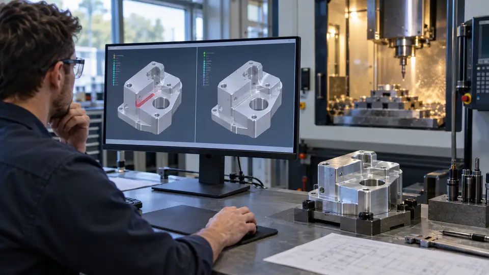
CAD configurations, model states, suppression rules, and display representations let one design file represent several products or manufacturing conditions. They are useful inside a controlled CAD or PLM environment, but they can become dangerous at a CNC supplier boundary. The supplier may open a different active state, export the wrong member, omit a required body, or quote a simplified representation that was never intended to define the finished part.
This CAD configuration CNC manufacturing guide explains how to release one unambiguous geometry state, verify neutral-file exports, control family members and manufacturing stages, and keep CAM, drawings, BOM data, and revisions synchronized. The issue is not a particular CAD brand. It is whether the transmitted files identify the same intended product.
Understand What a CAD State Can Change
Modern CAD systems can vary more than feature visibility. A state may change dimensions, feature suppression, component inclusion, materials, custom properties, part numbers, tolerances, assembly positions, simplified geometry, or bill-of-material information. Autodesk describes Model States as capable of representing manufacturing stages, simplification levels, product families, and adjustable products, with unique dimensions, components, properties, and suppression states.
Other systems use names such as configurations, arrangements, representations, members, variants, or family tables. Do not assume equivalent behavior. In some systems a hidden component remains part of the product; in others a suppressed component is excluded from the BOM. A display state may change only what is visible, while a configuration changes the physical definition.
Before release, identify exactly what the selected mechanism controls in the source CAD version.
Distinguish Hidden from Suppressed
Hidden normally means geometry remains present but is not displayed. Suppressed generally means a feature or component is removed from the active regeneration or assembly state. The distinction affects export, mass properties, interference, drawings, and BOMs.
A hidden fastener may still export depending on settings. A suppressed hole may disappear from the solid body entirely. A simplified representation may replace a detailed subassembly with an envelope. The viewer screenshot can look similar while the manufacturing data differs.
Never tell a supplier to “machine what is visible” unless visibility is an explicitly controlled product-definition rule. Release a defined state and verify the exported result.
Name the Released Configuration Explicitly
The RFQ manifest should identify:
- source CAD application and version;
- source document ID, part number, and revision;
- configuration or model-state name;
- family member or parameter row;
- active assembly arrangement where applicable;
- neutral export file name and format;
- drawing sheet/view state;
- quantity and delivery requirement for that state.
Avoid default names such as Configuration1, Copy of Default, or Model State 2 in released data. Use meaningful controlled names tied to product identity, such as PN-4286-REV-C-PRODUCTION or a PLM-managed variant code.
The name alone is not proof. Store the configuration identity in the manifest and, where possible, in the model’s controlled properties and drawing title block.
Release One Part Number per Manufacturable Definition
If two configurations are not interchangeable as purchased parts, they usually need distinct part numbers or another unambiguous ordered identity. A long and short bracket, left and right housing, or drilled and undrilled state should not rely solely on someone selecting a drop-down menu.
Some family systems legitimately use a master and members. In that case, the purchase order must identify the exact member, revision, and quantity. The supplier should receive a member-specific neutral file and drawing when practical.
Do not assign the same part number and revision to two geometries unless the organization’s formal product-definition rules explicitly permit that relationship and every downstream system can preserve it.
Separate Manufacturing Stages from Finished-Part Variants
A model may contain as-cast, rough-machined, heat-treated, finish-machined, and assembled states. These represent process stages, not alternative finished products. Label them accordingly and state which state governs the purchased output.
Stage models can improve fixture, stock, and process planning, but they must not conflict with the final definition. An in-process model may include sacrificial stock, plugged holes, temporary tabs, or omitted finishing allowance. Mark it as reference or supplier-process data unless the buyer deliberately controls that operation.
The final drawing and model should define the accepted product. The supplier may propose its own intermediate geometry unless the buyer has a validated reason to mandate it.
Handle Simplified and Intellectual-Property-Reduced Models
An assembly may be simplified to improve performance or protect proprietary geometry. Envelopes, shrinkwraps, defeatured bodies, and substitutes can be useful for clearance and interface communication. They may omit fasteners, gaps, internal components, mass distribution, or service access.
Label a simplified model as such. State which interfaces are authoritative and which geometry is approximate. Do not use it to create production toolpaths unless it contains the complete purchased-part definition.
For supplier communication, create a minimum necessary interface model separate from the released component model. The interface file can show mating envelopes and keep-outs while the part file provides full machinable geometry.
Verify Drawings Against the Selected State
Drawing views can reference a particular configuration or model state. When the model changes, a view may remain linked to an unexpected state, show suppressed features incorrectly, or carry dimensions that refer to geometry no longer present.
Before release:
- regenerate every drawing view;
- confirm view labels and configuration references;
- check section, detail, and auxiliary views;
- confirm BOM and parts-list content;
- verify dimensions and annotations remain attached to the intended features;
- compare mass and envelope with the released model;
- open the final PDF independently.
A correct native drawing can still create a stale PDF if the export was not regenerated after the state changed.
Validate the Neutral Export
STEP, Parasolid, IGES, DXF, and other neutral files do not necessarily preserve the source system’s configuration logic. The exporter usually writes the currently selected geometry or chosen bodies. Treat the neutral file as a snapshot that requires verification.
Open it in an independent viewer or receiving CAD system and check:
- body and component count;
- solid versus surface state;
- units and overall extents;
- orientation and origin;
- holes, pockets, bosses, fillets, and suppressible options;
- assembly positions and duplicated/missing components;
- part names and properties where needed;
- PMI and annotations if they are intended to transfer;
- mass or volume comparison within an explained method.
Record the export settings and selected state. A checksum can later confirm that the verified file is the one transmitted.
Use Geometry Fingerprints for Critical Releases
For high-risk or automated exchange, store simple geometry facts alongside the file. Useful fingerprints include bounding-box dimensions, solid count, volume, surface area, mass using a stated density, and coordinates of selected interface features.
These checks can catch a wrong configuration, unit error, missing body, or stale export before programming. They do not prove complete geometric equivalence; two different designs can share volume and extents. Use them as fast controls plus visual and engineering review.
Where the receiving system supports more rigorous comparison, run a geometry-difference check between the released source and imported neutral model. Record the tolerance and treatment of analytic versus faceted geometry.
Control Suppression Driven by Parameters or Rules
Some features are suppressed conditionally based on dimensions, equations, options, or automation. A parameter change can therefore alter more than the obvious size. Regenerate the complete model and review rule outputs before release.
Audit dependencies:
- features that reference geometry suppressed in another state;
- equations shared across family members;
- design tables or spreadsheets with stale calculations;
- scripts or macros that run only on one workstation;
- external references that resolve differently outside the design network;
- defaults that change after a CAD-version upgrade.
Freeze or package required references according to the CAD and PLM procedure. A supplier should not need access to an engineer’s local spreadsheet to reproduce released geometry.
Watch Suppressed Holes, Threads, and Finish Allowances
Small manufacturing features are easy to lose in a wrong state. Examples include tapped holes, inserts, dowels, vent grooves, drain holes, masking reliefs, and machining allowance. Their absence may not be apparent in a thumbnail or overall mass.
Create a configuration delta table listing every feature intentionally added, removed, or changed between ordered variants. Focus on functional and process-sensitive details. The table is especially useful for left/right or option families whose shapes mostly overlap.
| Variant difference | Verification | Manufacturing consequence |
|---|---|---|
| Hole pattern | Count, size, location, thread note | New drilling/tapping and inspection program |
| Pocket or boss | Geometry comparison and local section | Tool access, stock, cycle time |
| Finish allowance | Section check and stage label | Process sequence and final dimension |
| Insert or component | BOM and assembly review | Purchasing, installation, traceability |
| Mirror or handed state | Datum and coordinate verification | Fixture orientation, marking, error-proofing |
Do not rely on file size or modification date to identify these differences.
Manage Left-Hand and Right-Hand Parts
Mirrored hardware is a frequent configuration error. A CAD mirror can create a geometrically opposite part while retaining the same thread handedness, datum labels, markings, or orientation assumptions unintentionally.
Assign clear part identities. Verify asymmetric functional features, connector orientation, text, countersinks, spotfaces, keyways, and mating components. Include a visual orientation view and inspection characteristic that differentiates the pair.
Use error-proofed fixtures and packaging labels. A CMM report should name the actual handed part, not a generic family program with an operator-entered note.
Control Assembly Configuration and BOM
At assembly level, suppression can remove components from the active structure or only reduce display. Confirm the BOM generated for the released state. Compare it with the drawing parts list, procurement record, and neutral assembly.
Check quantities, alternates, phantom or reference components, hardware, purchased items, and substitute representations. If the supplier is machining one part only, provide enough assembly context to understand interfaces without treating the reference assembly BOM as ordered scope.
For multi-level configurations, verify child-state selection. The top assembly may activate an unintended default state in a subcomponent after references are updated.
Keep CAM Linked to the Released State
CAM should reference a controlled snapshot or released configuration. Record source part, revision, configuration, neutral-file hash, and CAM program revision. If the model state changes, force a delta review before regenerating toolpaths.
Associative CAM can update automatically when geometry changes. That saves time but can also move operations to unintended faces or suppress toolpaths without a clear failure. Recalculate, simulate, and review affected setups after every source change.
Do not reopen a prior program merely because the file name matches. Compare the current product definition, stock, setup, fixtures, and features first.
Keep Inspection Programs Synchronized
Inspection drawings, balloons, CMM programs, functional gages, and report templates must identify the same configuration. A program for the long variant can run on the short variant and still measure several features plausibly.
Use configuration-specific program selection and error-proofing. Verify at least one distinguishing characteristic before executing the full routine. Review datum and feature identifiers after suppressed geometry changes; CAD associativity can remap labels unexpectedly.
Retain actual values and sample identity. The record should reveal which state was measured without relying on folder location.
Account for Mass Properties and Simulation
Suppressing internal components, fasteners, or detailed features changes calculated mass, center of gravity, inertia, and sometimes stiffness. A simplified model created for graphics performance should not silently become the source for robot payload, transport, or structural decisions.
State which configuration controls each analysis. If substitute geometry uses equivalent mass properties, document the values and limitations. Recalculate after a family member or material changes.
For machined lightweight parts, verify that the manufacturing state includes all pockets and reliefs used in the mass budget. Conversely, do not quote unnecessary internal detail from a simulation-only model.
Manage Product Changes
When a feature or state changes, the revision review should identify every affected member. A change to a master sketch may propagate into several variants; a local override may affect only one. Record scope explicitly.
Compare previous and new released exports for each affected member. Update drawings, BOMs, CAM, inspection, qualification, and supplier packages. Define work-in-progress and inventory effectivity.
Do not use a new configuration name as a substitute for a revision when the product definition changed. Names organize states; revisions record approved changes.
Package Native CAD Responsibly
If the supplier needs native CAD, include referenced parts, design tables, library features, and controlled dependencies according to licensing and IP rules. Use the CAD system’s package-and-copy function when appropriate, then test the package on a clean environment.
Remove unrelated configurations and proprietary context that the supplier does not need, but do not strip information required to regenerate the selected state. Mark the transmitted native file as authoritative or reference and define the conflict rule with the neutral model and drawing.
For long-term supplier access, a verified neutral snapshot is often more reliable than requiring the exact authoring environment years later.
Audit a Configuration Family Before Release
Do not review each member only in isolation. Create a matrix with members in columns and controlled differences in rows. Compare part number, material, mass, bounding box, suppressible features, hole and thread counts, interface locations, finish, drawing, and intended quantity. Unexpected identical values can reveal a state that did not regenerate; unexpected differences can reveal a parameter or property applied at the wrong scope.
Select representative members at the minimum, maximum, and transition values of parameter-driven families. A rule may work for most sizes and fail where a fillet consumes a wall, a hole breaks into a pocket, or a feature switches suppression state. Regenerate those boundary members and inspect them directly.
For assemblies, compare component occurrence counts and persistent identity, not only total BOM rows. A suppressed washer, duplicated fastener, or substituted subassembly can leave the total mass nearly unchanged while altering assembly. Review mating and clearance at the active positions used for manufacturing.
Record who performed the audit, source version, date, and exceptions. Approval should cover the named members, not every mathematically possible variant unless the design system has been validated across that full range.
Use a Supplier Import Report
Ask the receiving supplier to return a short import report before programming. It should identify the received files, source and target systems, import date, units, bodies, solids versus surfaces, configuration identity, translation messages, and any repaired geometry. For assemblies, include component counts and missing references.
The supplier should state whether the neutral model opened as a watertight solid and whether any feature needed healing, stitching, replacement, or simplification. A successful status icon does not prove that every small face and edge transferred correctly.
Compare the report with the buyer’s verified export record. Resolve differences before the supplier estimates detailed tooling or creates toolpaths. If a repair is approved, preserve both the original and repaired file, document what changed, and decide which geometry becomes the manufacturing reference.
For repeat orders, compare the current import report with the earlier one. A different CAD translator version or tolerance setting can change topology even when the released source has not changed. Reuse of CAM should be conditional on that comparison.
Close every import exception with a named engineering disposition. A harmless change in face identifiers may require only CAM reassociation and simulation, while an open edge, missing pocket, changed assembly position, or altered PMI record may require a corrected export. State which file the supplier will actually use after the review. If repaired geometry becomes the manufacturing reference, assign it controlled identity and preserve the buyer’s approval; otherwise later inspection and repeat orders can revert to the original defect.
Prepare a Quote-Ready Release Package
Include:
- part number, revision, and exact configuration/model-state identity;
- verified neutral 3D model;
- controlled 2D drawing or validated model-based definition;
- manifest listing every file, role, revision, and checksum;
- configuration delta table for related ordered members;
- assembly interface model labeled as reference where applicable;
- material, finish, quantities, and inspection requirements;
- conflict authority and clarification process;
- screenshots only as navigation aids, not product authority;
- supplier acknowledgment of the active state.
Ask the supplier to report its imported body count, units, extents, and any translation or feature ambiguity.
Common Failure Modes
A supplier machines the default configuration
Contain the work, compare it with the ordered state, and correct the release and program-selection controls. Do not merely rename the default.
A suppressed hole appears on the drawing
Check the drawing view’s referenced state and regeneration status. Align the released model, view, PDF, balloon list, and inspection program.
A neutral file omits an assembly component
Verify source selection, visibility/suppression behavior, export options, and body count. Re-export and independently inspect the complete file.
A simplified model is quoted as the finished part
Identify its intended role and issue a complete production definition. Requote if the missing geometry affects stock, access, time, or inspection.
A CAD upgrade changes rule behavior
Regenerate each released member, review errors and dependent features, compare geometry fingerprints, and reissue verified exports. Do not assume automatic migration preserves every state.
Final Release Checklist
Before sending the CNC RFQ, confirm that:
- the selected CAD state has a meaningful controlled identity;
- product variants have unambiguous part numbers and revisions;
- hidden, suppressed, simplified, and manufacturing-stage geometry are distinguished;
- drawing views and BOMs reference the intended state;
- neutral exports have been opened and checked independently;
- body count, units, extents, orientation, and key features are correct;
- configuration deltas identify critical differences;
- CAM and inspection programs will link to the released snapshot;
- mass and simulation results use the correct state;
- native dependencies are packaged or removed intentionally;
- changes carry effectivity across all affected members;
- the supplier acknowledges the state and reports import exceptions.
Release Geometry, Not a Drop-Down Choice
Configurations are excellent design tools when their state survives into manufacturing records. At the supplier boundary, the buyer should release one verified geometry for each ordered identity, define its relationship to the drawing, and preserve a traceable snapshot for CAM and inspection.
Send QuickCNCs the verified neutral model and controlled 2D drawing with the exact variant, revision, quantities, material, finish, and inspection plan. The team can review model integrity and manufacturing access through CNC milling services and rapid prototyping. Submit the coherent package at Request a Quote.
References
- Autodesk: Introducing Model States — examples of state-dependent dimensions, properties, components, and suppression.
- Autodesk: Configurations and Representations — distinctions among configurations and representation mechanisms.
- NIST Digital Thread for Manufacturing — product-definition interoperability and traceability across manufacturing.