
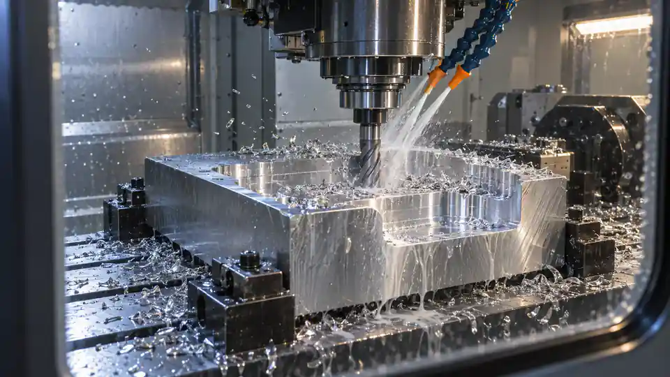
Two parts made from the same alloy and finished to the same envelope can have very different prices. The difference is often machine time: how much stock must be removed, how fast each operation can remove it, how many times the machine must reposition, and how much noncutting time is required for tools, probing, loading, and inspection.
This CNC cycle time cost guide explains how suppliers estimate cutting time and material removal, why material-removal rate (MRR) is only one part of the quote, and what buyers can change without weakening the design. It provides formulas and examples for comparing quotes, but it does not claim universal shop rates or feeds and speeds. Actual values depend on machine, tooling, material, geometry, workholding, quality requirements, quantity, and local overhead.
Separate Cycle Time from Lead Time
Cycle time is the elapsed production time for a part or operation under a defined method. Lead time is the calendar duration from order to delivery. Lead time also includes material procurement, engineering review, programming, fixture manufacture, queue, outside processing, first-article approval, inspection, packaging, and transport.
A ten-minute cutting cycle does not promise a ten-minute delivery. Conversely, a long calendar lead time does not prove the part is expensive to machine. Quote reviews should keep machine hours, labor hours, and calendar gates separate.
What a CNC Cycle Contains
The useful unit is not spindle-on time alone. A complete repeat cycle can contain loading, datum location, probe routines, rapid travel, spindle acceleration, tool changes, cutting, chip clearing, in-cycle inspection, deburring at the machine, unloading, and periodic allowances for insert indexing or cleaning.
For a multi-operation part, total repeat cycle can be represented as:
Tpart = Σ(Tcut + Tposition + Ttool-change + Tprobe + Tload/unload) + allocated periodic time
Nonrecurring programming, setup, and first-article work should normally be shown separately or amortized over the quoted lot.
Material-Removal Rate
MRR describes the volume of material removed per unit time during cutting. For milling, a simplified relationship is:
MRR = radial width of cut × axial depth of cut × table feed
If width and depth are in millimeters and feed is millimeters per minute, MRR is cubic millimeters per minute. In turning, a simplified volumetric relationship depends on cutting speed, feed per revolution, and depth of cut. CAM systems often estimate volume removed from stock and toolpath engagement more directly.
MRR is useful for roughing comparisons, but it is not an invoice formula. It excludes air cuts, approach moves, tool changes, finishing, probing, and handling, and maximum achievable rate changes throughout the toolpath.
A Simple Roughing-Time Estimate
Suppose a pocket requires removal of 240,000 mm³. If the stable average MRR during engaged roughing is 12,000 mm³/min, theoretical engaged cutting time is 20 minutes. If entry, repositioning, corner slowdowns, tool changes, and chip clearing add eight minutes, that operation’s modeled machine time is 28 minutes before setup or inspection.
Using a catalog maximum MRR of 30,000 mm³/min would predict eight minutes of cutting and understate the real cycle. Quote assumptions should use an achievable average for the actual geometry, tool engagement, reach, spindle power, rigidity, coolant, and chip evacuation.
Stock-to-Part Volume Is Only the First Clue
Buyers can compare the raw stock volume with the finished part volume to understand how much material disappears, but equal removal volume can require different time. One open pocket can be cleared with an efficient high-feed or adaptive strategy. The same volume divided among deep slots, small corners, intersecting bores, and closed cavities requires smaller tools and slower motion.
CAD mass properties help, but a supplier must interpret machinable regions, setups, and remaining walls. Request a design-for-manufacturability explanation when the quote attributes a large share of price to removal.
Machine Power and Torque Limit MRR
Cutting consumes power. The feasible removal rate depends on the material’s specific cutting energy, spindle power available at the programmed speed, drive efficiency, and stability of the machine-tool-workpiece system. Low spindle speed can expose a torque limit; high speed can expose a power or tool-balance limit.
A nominal 20 kW spindle does not deliver 20 kW at every speed or continuously. Toolholder interface, cutter diameter, number of teeth, stickout, insert geometry, machine structure, and workholding determine whether that power can be used productively.
Tool Engagement Changes Along the Path
Constant radial engagement strategies can stabilize cutter load during roughing, but corners, narrow channels, entry moves, and remaining-stock conditions still change engagement. CAM software may reduce feed to protect the tool or maintain chip thickness. Rest machining with a smaller cutter adds passes to reach material left by the larger tool.
Ask whether the estimate is based on a programmed toolpath simulation or a simple volume-rate assumption. For mature repeat work, actual run data are more reliable than either.
Material Condition Changes Cutting Performance
Alloy name alone does not set speed. Temper, hardness, heat treatment, casting skin, scale, inclusions, grain condition, residual stress, and raw-stock quality affect tool life and stability. Aluminum 6061-T6, annealed stainless steel, precipitation-hardened stainless, titanium, and filled engineering plastics require very different strategies.
Buyers should specify material grade, specification, condition, stock form, and certification. A quote based on free-machining stock is not comparable with one based on aerospace-certified plate, forged billet, or material requiring ultrasonic inspection.
Roughing and Finishing Serve Different Purposes
Roughing removes volume efficiently and leaves controlled stock. Finishing establishes size, geometry, texture, and appearance. A high roughing MRR cannot be carried into a thin-wall finishing pass or a bearing bore requiring stable geometry.
Finishing time grows with surface area, number of features, step-over, path smoothing, spring passes, inspection feedback, and tool changes. Tight tolerances may require semi-finishing, thermal stabilization, unclamp-and-relax steps, or grinding after machining.
Small Tools Reduce Productivity
Internal corner radii, narrow slots, micro-holes, and engraved details force smaller cutters. Small tools have limited flute volume and stiffness; their feed rate and depth of cut may be far below those of the roughing tool. They can also require high spindle speed and cautious entry.
One small corner can add a rest-machining operation across multiple depth levels. Increasing a nonfunctional corner radius or widening a slot may allow a larger tool and reduce both cutting time and breakage allowance.
Tool Reach Can Dominate Cycle Time
A long-reach tool bends more under cutting force. The supplier may reduce radial engagement, axial depth, feed, or material per tooth and add step-downs or finishing passes. Tool chatter can damage surfaces, accelerate wear, and make cycle estimates unreliable.
Deep cavities also obstruct coolant and chip evacuation. A design change that opens access, reduces depth, enlarges a corner radius, or permits machining from another side can save more time than optimizing nominal MRR.
Five-Axis Motion May Reduce Setups but Not Always Time
Five-axis machining can reach multiple faces in one clamping, reduce fixture transfers, and maintain a short tool orientation. That can improve accuracy and total throughput. Simultaneous five-axis paths can also require smaller step-over, extensive verification, and slower rotary motion.
Compare the complete route. A three-axis process with two simple fixtures may be faster for a prismatic part, while a five-axis route may be superior for complex access or datum continuity. Machine hourly rate and cycle time must be evaluated together.
Turning Cycle-Time Drivers
For turned parts, diameter, length, stock allowance, cutting speed, feed per revolution, depth of cut, number of passes, and rapid travel determine much of the cycle. Grooves, threads, deep bores, thin walls, parting, live-tool milling, and subspindle transfer add operations.
Bar-fed production can reduce loading time, while billet or chuck work may require manual handling and soft jaws. Long slender shafts may require a tailstock, steady rest, lower feed, and additional straightness control.
Drilling and Holemaking Time
Hole cost depends on diameter, depth-to-diameter ratio, quantity, entry surface, breakthrough, required size and position, thread, and access. Spot drilling, peck cycles, high-pressure coolant, reaming, boring, thread milling, tapping, countersinking, and deburring can each add time.
A drawing with fifty nominally identical holes may still require several tool groups if depths, fits, threads, or orientations differ. Standardizing sizes and thread forms reduces tool changes and programming complexity.
Tolerances Affect More Than Feed Rate
A tight dimension can require a different machine, stabilized temperature, probing, wear compensation, multiple finishing passes, special workholding, or a secondary grinding or honing operation. The cost may appear as added cycle time, setup time, inspection time, or outside-process minimum charge.
Identify the few limits tied to function. Relaxing an irrelevant three-decimal-place dimension can improve price; relaxing a datum, fit, sealing, or safety requirement without analysis can create a much larger downstream cost.
Surface Finish Extends Toolpaths
Surface texture requirements influence tool geometry, feed per tooth or revolution, step-over, cusp height, and number of finishing passes. A cosmetic surface may also require consistent cutter direction, protected handling, blending, polishing, or a separate appearance standard.
State Ra or another defined parameter only where function requires it, and identify the evaluation length and direction when relevant. Do not apply one fine finish to the entire model by default.
Workholding Time and Accessibility
Fixture loading, clamping, locating, probing, and cleaning are part of the repeat cycle. A part needing six independent vises or careful manual alignment consumes more time than one located repeatably in a dedicated fixture. Low quantity may not justify automation; high quantity may justify hydraulic, pneumatic, tombstone, pallet, or robot loading.
Workholding also limits cutting force. Thin or flexible features can distort under clamp load, forcing smaller cuts. Accessible, stable datum pads and clamp regions help the supplier use a faster route.
Tool Changes and Machine Noncutting Motion
A complex part may use dozens of tools. Each change adds time, but the larger cost can be presetting, tool life management, sister tools, and verification. Tools with similar function may be consolidated if tolerances and geometry permit.
Rapid motion and acceleration matter on short features. A toolpath containing thousands of tiny segments may never reach the programmed feed. Controller look-ahead, smoothing, rotary-axis limits, and safe-clearance moves affect actual time.
Probing Can Save or Add Time
On-machine probes locate stock, set work offsets, verify tools, and measure features between operations. They add minutes to the cycle but can prevent scrap, reduce manual alignment, and support unattended production. For critical features, probing may enable controlled compensation before the final cut.
Probe results are not automatically final inspection. Thermal conditions, stylus access, machine geometry, calibration, and uncertainty may make separate inspection necessary. Quote reviews should distinguish process control from acceptance evidence.
Scrap and Tool-Life Risk Enter the Price
Suppliers price expected yield, consumable tools, and disruption risk. A long cycle with a fragile tool near the final operation exposes more accumulated value than a robust early operation. Difficult chips, interrupted cuts, abrasive material, or variable stock can shorten tool life.
A credible quote may include conservative parameters until the process is proven. Repeat-order data can support later improvement. Buyers should not demand an unsupported theoretical rate and then treat tool failures or scrap as solely the supplier’s problem.
Machine Rate Is Not the Same as Profit
An hourly machine rate can include depreciation or lease, facility, energy, maintenance, tooling infrastructure, software, indirect labor, quality systems, and overhead. Different machines have different rates and productivity. A faster, higher-rate machine can produce a lower part cost if it removes setups or finishes sooner.
Direct labor may be concurrent with machine cutting or may attend the whole cycle. Unattended operation changes economics but requires reliable chip control, probing, tool monitoring, and material handling.
Convert Cycle Time into Recurring Cost
A simplified recurring conversion is:
Machine cost per part = cycle hours × machine rate
Direct labor cost per part = attended labor hours × labor rate
Then add allocated tooling, consumables, inspection, outside processes, scrap allowance, packaging, and overhead according to the supplier’s costing system. A buyer usually does not need confidential shop rates, but does need a consistent breakdown of nonrecurring and recurring drivers.
| Cost element | Typical basis | Useful buyer question |
|---|---|---|
| Programming/CAM | Nonrecurring engineering hours | Is it charged once and retained for repeats? |
| Setup | Hours per batch or operation | How many setups and parts per setup? |
| Cutting cycle | Machine minutes per part | Which features dominate time? |
| Tooling | Per job, per tool life, or included | Are special cutters or sister tools required? |
| Inspection | Program, first article, and per-lot time | Which results are included? |
| Scrap/risk | Expected yield allowance | Which requirements create the risk? |
| Outside process | Lot minimum plus unit charge | Does batch size affect the allocation? |
Setup Cost Changes with Quantity
If programming and setup total $900 and repeat conversion cost is $45 per part, a quantity of 10 carries $90 setup allocation per part before recurring cost; a quantity of 100 carries $9. This is why prototype and production unit prices differ even when the cycle stays unchanged.
Quantity breaks should state whether nonrecurring work is included, whether material must be purchased in a larger minimum, and how many releases share the setup. Do not assume the lowest high-volume unit price applies to small scheduled releases.
Capacity and Utilization Affect Commercial Quotes
Two shops may estimate the same technical cycle yet quote different delivery or price because their suitable machines have different capacity, automation, queue, or opportunity cost. An urgent job may require overtime or displacing planned work.
Capacity is a commercial factor, not proof that one process estimate is wrong. Ask which machine class and routing support the commitment, whether an alternate is qualified, and what schedule assumptions apply.
How to Compare Supplier Estimates
Request a compact operation-level summary instead of proprietary CAM files: stock form, number of setups, major operations, estimated repeat cycle, setup hours, special tooling, inspection scope, outside processes, yield assumptions, and exclusions.
Normalize quantities, material specification, final condition, inspection records, packaging, and delivery terms. A low quote that omits first-article documentation, finishing, or secondary deburring is not equivalent to one that includes them.
Verify Estimates with Simulation and Run Data
CAM simulation can estimate toolpath duration and identify collisions, rapid moves, and engagement changes, but its clock is only as accurate as the machine model. Controller acceleration, spindle ramp, tool-change duration, probing macros, pallet exchange, operator actions, and programmed dwell must be represented. Some systems report feed time without realistic acceleration, which is optimistic on paths made of many short moves.
During first-article manufacture, record actual start and stop points for setup, cutting, probing, tool handling, and external inspection. Compare each operation with the estimate and explain large differences. A slower first piece may include proving and adjustment that should not be assigned unchanged to repeat production; an unstable tool-life result may justify a recurring allowance.
For repeats, maintain a revision-controlled standard time tied to the CNC program, machine class, fixture, and quality plan. Re-estimate after a drawing change, alternate material, machine transfer, new toolpath, or changed inspection scope. This feedback makes later quotations more reliable without exposing proprietary programming details.
Record the lot quantity and number of conforming pieces used for the comparison. Dividing total elapsed shop time by only shipped pieces can hide rework and scrap, while dividing by every attempted blank can overstate a stable cycle after a corrected startup problem. Keep normal production, engineering trials, and recovery work identifiable.
Design Changes That Often Reduce Time
- Start from near-net stock or a profile closer to the final envelope when quantity supports it.
- Open deep cavities and provide cutter access.
- Increase nonfunctional internal corner radii.
- Reduce extreme depth-to-width and depth-to-diameter ratios.
- Standardize hole, thread, and tool sizes.
- Provide stable datum and clamping surfaces.
- Limit fine surface finish to functional areas.
- Concentrate tight tolerances on true interfaces.
- Permit larger roughing tools and realistic fillet transitions.
- Review whether five-axis access can remove setups.
Each change must be checked against strength, fatigue, sealing, assembly, appearance, and qualification requirements.
Information to Include in the RFQ
Send the 3D model and controlled 2D drawing with consistent revision identity. State material specification and condition, raw-stock restrictions, quantity and releases, finish, critical features, inspection records, packaging, and required date. Identify approved substitutions or prohibit them explicitly.
Ask suppliers to explain the top three cycle-time drivers and suggest alternatives with quantified effect where possible. A good DFM response connects a proposed geometry or tolerance change to a process route, not just a percentage discount.
Questions for a Quote Review
- What stock size and form are assumed?
- How much material is removed and which operations dominate machine time?
- How many setups and manual load events are included?
- Which features require small or long-reach tools?
- What inspection occurs in-cycle and after machining?
- Which costs are nonrecurring, per batch, or per part?
- What tool-life and yield assumptions materially affect price?
- Does the selected machine reduce setups enough to justify its rate?
- What design changes would shorten the cycle without changing function?
- Which assumptions must remain fixed for repeat pricing?
Practical Review Checklist
- Distinguish cutting time, total repeat cycle, setup time, and calendar lead time.
- Calculate removed volume but do not treat maximum MRR as average productivity.
- Include finishing, small tools, reach, holes, and noncutting motion.
- Account for material condition, power, rigidity, coolant, and chip control.
- Include loading, probing, tool changes, inspection, and periodic maintenance.
- Separate one-time programming and fixtures from recurring conversion.
- Normalize quote scope before comparing unit prices.
- Use actual run data for repeat jobs and revision-control the baseline.
- Challenge requirements that dominate time but do not protect function.
- Preserve critical tolerances and evidence even when pursuing cost reduction.
The Practical Cost Decision
MRR is a useful engineering measure for engaged roughing, while cycle time is the operational measure that connects the whole route to cost. Neither should be considered alone. The least expensive route balances stock, machine capability, tooling, access, setup count, quality evidence, and quantity.
Buyers get better comparisons by asking what consumes minutes and why, then changing the few design or scope choices that dominate the route. To review a part’s likely process and cost drivers, send the 3D model, controlled drawing, quantities, and required evidence through Request a Quote.