
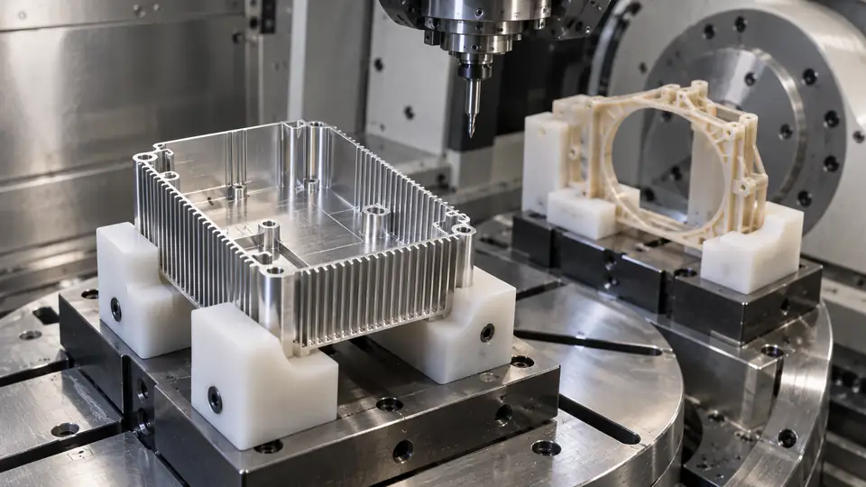
Thin walls make a part light and compact, but they also turn the workpiece into a flexible member. Cutting force, clamp pressure, residual stress, heat, and even inspection support can move the wall during manufacture. A feature may measure correctly while clamped and spring out of tolerance after release.
This thin wall CNC milling design guide explains aluminum and plastic proportions, material behavior, workholding, toolpaths, thermal control, deburring, and free-state inspection. It does not set one universal minimum thickness. Feasibility depends on wall height and span, neighboring support, material, tolerance, finish, access, quantity, and process route.
Think in Ratios, Not Thickness Alone
A 1 mm wall only 5 mm high behaves differently from a 1 mm wall 100 mm high. Height-to-thickness, unsupported span-to-thickness, pocket depth, and remaining base thickness are better risk indicators than thickness alone. Curvature, ribs, corners, and flanges can add stiffness.
Give the supplier the complete geometry and functional loads. A statement such as “we machine 0.5 mm walls” says little without material, span, tolerance, setup, and inspection state.
Aluminum and Plastics Fail Differently
Aluminum alloys are relatively stiff and conductive but can release residual stress, form burrs, and distort after asymmetric removal. Engineering plastics have much lower modulus, higher thermal expansion, lower softening temperature, and can absorb moisture or creep under clamp load.
The same wall geometry cannot use the same feeds, fixtures, cooling, or inspection timing. Material grade and condition must be fixed before DFM.
Common Aluminum Choices
6061-T6 is widely available and generally machinable. 7075-T6 provides higher strength and often good machining behavior, but material cost, corrosion, and application constraints differ. Cast tooling plate can offer dimensional stability for plate-like components, while not necessarily meeting a wrought structural specification.
Do not substitute solely to improve machining. Verify strength, fatigue, corrosion, anodizing response, conductivity, temperature, certification, and product-form requirements.
Common Engineering Plastics
POM/acetal, PEEK, nylon, PTFE, polycarbonate, UHMW-PE, and filled grades have distinct stiffness, heat, moisture, abrasion, and chip behavior. Fiber reinforcement can increase stiffness and wear tools while creating anisotropy or edge breakout. PTFE and UHMW-PE are particularly compliant; unfilled PEEK behaves differently from carbon-filled PEEK.
Specify exact resin, grade, filler, color where relevant, product form, conditioning, and certification. “Plastic” is not enough for a reliable quote.
Residual Stress in Aluminum Stock
Rolled plate and extruded bar contain residual stresses from manufacture and heat treatment. Removing material from one side changes the balance, causing bow or twist. Thin frames and covers are especially sensitive because little stiffness remains after roughing.
Use stress-relieved product when appropriate, remove stock symmetrically, rough both sides, allow relaxation, and finish from stable datums. Extra stock and an intermediate operation may cost less than repeated rework.
Residual Stress in Plastic Stock
Extruded or molded plastic plate and rod can also contain stress. Machining releases it, and frictional heat can add new distortion. Annealing may help some materials and sizes, but the cycle, support, cooling rate, and material manufacturer’s recommendations matter.
Ask whether stock is compression-molded, extruded, annealed, or otherwise conditioned. Product form affects flatness and stability even when the polymer designation matches.
Moisture Conditioning
Nylon and other hygroscopic polymers change dimensions and properties with moisture. A part measured dry after machining can move after conditioning or service exposure. State whether requirements apply in an as-machined, dry-as-molded, conditioned, or service-equilibrated state.
Control storage, soak or conditioning, and inspection timing. Packaging may need a moisture barrier or controlled environment. Do not demand metal-like tolerance without defining moisture state.
Thermal Expansion
Plastics generally expand much more than metals. Heat from cutting, a warm shop, a hand, or an inspection room transition can change a thin feature materially. Aluminum also needs temperature control for tight tolerances, especially over large spans.
Define reference temperature and stabilization. Use sharp tools and low-heat cutting, and avoid measuring immediately after aggressive machining unless a validated compensation method applies.
Design Ribs Instead of Uniformly Thickening
A rib can increase bending stiffness with less mass than thickening the entire wall. Place ribs along load paths and unsupported spans, with transitions that avoid sharp stress concentration and allow cutter access. Curved walls, beads, returns, and flanges can provide similar benefits.
The rib itself must be machinable. Provide root radii, adequate channel width, and room for a toolholder. A dense rib network can increase cycle and trap chips.
Use Generous Internal Radii
Sharp internal corners force small cutters and concentrate stress. Larger vertical radii permit stiffer tools and smoother motion. Floor radii can support the wall-base transition but may interfere with mating parts.
Specify only the corner regions that require clearance. Relief in a mating component or a small edge break can often permit a larger machining radius.
Avoid Abrupt Thickness Changes
A thick boss connected directly to a thin wall can cause uneven stiffness, stress release, and thermal response. Blend transitions with radii, tapers, or ribs. For plastic, consider sink, molded-stock stress, and local heat accumulation.
If a boss carries a fastener, analyze bearing load, thread engagement, insert installation, and clamp force rather than choosing its size only from tool access.
Leave Support Until Late
Process sequence should preserve stiffness. Rough the surrounding material while leaving the wall or base thicker than final. Machine opposing sides in balanced steps, then finish the thin feature after major stresses and cutting loads have been reduced.
Sacrificial ribs, tabs, carrier frames, or a temporary base can support the part. Removing them is a controlled final operation with its own blend and inspection.
Roughing Strategy
Use a larger, shorter tool where possible and maintain stable engagement. Leave uniform finish stock; uneven stock makes the finishing cutter load change and pushes the wall unpredictably. Avoid burying a small tool in a corner.
For pocketed parts, alternate regions or sides to balance stress. Plan chip evacuation so recutting does not press chips against delicate walls.
Finishing Strategy
Low radial engagement and a sharp, appropriate-helix tool can reduce force. Multiple axial zones may prevent the full wall height from deflecting together. Climb direction, toolpath order, stock allowance, and cutter wear affect final size.
One spring pass may improve size; repeated passes can rub, heat the wall, or chase elastic deflection. Validate the minimum stable sequence with measured results.
Machine Both Sides of a Wall Deliberately
When two pockets create one wall, machining one side completely before the other can bend the remaining section. Leave balanced stock on both faces, alternate roughing, then finish in a controlled order. The accessible support changes after each pass.
If both sides carry tight profiles, agree which datum and free-state condition control. The last pass can move the first surface.
Tool Geometry for Aluminum
Sharp polished flutes, suitable rake, good chip space, and aluminum-compatible coatings or uncoated carbide reduce built-up edge. Tool runout matters because one flute can carry excess load. Coolant or air should evacuate chips without hydraulically bending a delicate wall.
Select diameter and flute length from access, but minimize unsupported tool length. A long tool deflecting into a thin wall compounds two flexible members.
Tool Geometry for Plastics
Plastic tools need sharp edges and chip evacuation. O-flute or polished geometries are useful in many polymers, while filled materials may require abrasion-resistant tooling. Too many flutes can trap chips and heat; too little support can tear the edge.
Avoid rubbing and dwell. Burr or fuzz behavior varies by resin and orientation. Confirm tool advice with the material and cutter supplier for the exact grade.
Coolant and Air Choices
Flood coolant helps aluminum cool and clear chips, subject to compatibility with later finishing or cleaning. Air or mist can support visibility and reduce hydraulic load. Plastics may react to coolant chemistry or absorb fluids, and compressed air can cool while moving a flexible feature.
The process must control heat without contaminating the product. For medical, vacuum, optical, or food applications, define approved fluids and cleaning evidence.
Workholding Without Distortion
Clamp from stiff regions and support near cutting loads. A flat plate clamped at corners can bow between them; a thin ring can become lobed in a three-jaw chuck. Broad soft contacts, vacuum, custom nests, potting, carriers, or sacrificial stock may help.
Use the minimum repeatable force. Document clamp sequence and pressure or torque for critical work. Measure after release, not only while the fixture is forcing the part nominal.
Soft Jaws and Conforming Nests
Machined jaws or nests distribute force over the part shape. Provide relief for burrs and chips so the component seats on intended locators. For plastic, avoid sharp locator contact that creeps or indents the surface.
Qualify nests for wear and cleanliness. A support that exactly matches nominal CAD can overconstrain a distorted blank; controlled clearance and datum contacts may be better.
Vacuum and Adhesive Fixtures
Vacuum spreads support across a broad area but requires sealing area and resistance to lateral force. Through-cuts, porosity, surface texture, and leaks reduce capacity. Tabs or low-force paths may remain necessary.
Adhesive, tape, wax, or potting can support very thin parts. Include cure, bond-line thickness, heat, removal, cleaning, residue, and material compatibility. These methods add time and validation even when cutting becomes easier.
Thin Rings and Turned Walls
Thin rings distort under chuck pressure and cutting force. Segmental soft jaws, expanding mandrels, pot chucks, sacrificial plugs, or controlled low-force clamping can improve roundness. Roughing may leave radial and axial stock for a later relaxed finish.
Specify free-state roundness, cylindricity, wall thickness, and diameter separately. A ring can measure round while held and become oval after removal.
Burrs and Edge Breaks
Thin aluminum edges form burrs and are easily rolled during manual deburring. Plastic edges may fuzz, smear, or chip. A generic large chamfer can consume a meaningful share of the wall thickness.
Define edge condition proportionately: break sharp edges, allowable chamfer or radius, protected functional edges, and no-go cosmetic regions. Prefer controlled toolpath deburring when it improves repeatability.
Surface Finish and Cosmetic Risk
Deflection and vibration create waviness, tool marks, or inconsistent reflection. Blasting can bend thin sections, polishing can round edges, and anodizing highlights surface variation. Plastic scratches easily during handling and can show stress whitening.
Use a visual standard, lighting, viewing distance, protected zones, and packaging requirements for cosmetic surfaces. Do not rely on an Ra value to define appearance.
Tolerance Strategy
Apply tight profile, flatness, parallelism, or thickness only where function requires it. Large free surfaces may need a restrained-state or assembly-state requirement if the mating structure intentionally flattens them. The drawing must distinguish free and restrained conditions under its governing standard.
Avoid stacking tight coordinate dimensions from unstable edges. Choose datums that can be located without bending the part and that represent assembly.
Free-State Inspection
Support can change the result. Define how the part rests, which points or surfaces support it, whether gravity direction matters, and whether clamps are prohibited or controlled. A CMM routine that probes aggressively can deflect plastic.
Use low-force probes, optical methods, air gages, fixtures, or functional checks as appropriate. Record temperature and conditioning. Compare measurement uncertainty with the tolerance.
Restrained-State Inspection
If function occurs while the part is fastened or located in an assembly, a defined restraint may be appropriate. The fixture should reproduce datum contacts and allowable force, not simply press the part until it passes.
Specify fastener pattern, torque or clamp force, sequence, support, and measurement access. Correlate the restraint tool with the real assembly.
A DFM Risk Matrix
| Condition | Main risk | Typical response |
|---|---|---|
| High wall-height/thickness ratio | Deflection and chatter | Ribs, shorter wall, staged low-force finish |
| Large thin pocket floor | Bow and oil-canning | Balanced removal, carrier or vacuum support |
| Thin aluminum frame | Residual-stress distortion | Stress-relieved stock, symmetric rough/finish |
| Hygroscopic plastic wall | Moisture-driven size change | Defined conditioning and packaging |
| Long plastic cycle | Heat and creep | Sharp tools, cooling, staged measurement |
| Thin ring | Clamp lobing | Conforming jaws, mandrel, free-state check |
The matrix starts the discussion; it is not a capability guarantee.
Cost Drivers
Thin-wall work can add conservative cutting parameters, extra setups, custom fixtures, sacrificial stock, stress relief or annealing, relaxation time, tool replacements, probing, free-state inspection, and yield allowance. Cosmetic protection and special packaging add handling.
Ask the supplier to connect each allowance to a feature and propose an alternative. A small increase in wall thickness or a rib can remove several costs at once.
Prototype and Production Routes
For prototypes, machining from stable oversize stock with a simple carrier may minimize lead time. For repeat production, dedicated nests, vacuum fixtures, palletization, near-net forms, or optimized material condition can lower cycle and improve yield.
Do not extrapolate one successful prototype to volume without reviewing process capability, tool life, stock variation, conditioning, and fixture durability.
Threaded Features in Thin Walls
A conventional tapped hole may not have enough engagement in a thin section. Evaluate screw diameter, material shear strength, service load, tightening torque, cycle life, edge distance, and required repair. A blind tap also needs drill-point and chip clearance that may exceed the visible thread depth.
Alternatives include a local boss, through-bolt and nut, threaded insert, helical insert, press-in hardware, or a separate bracket. Insert installation can expand or crack a weak wall, and thermal insertion can distort plastic. Define hole preparation, installation side, pullout or torque test, and whether hardware is installed before final inspection.
Keep threads away from the thinnest unsupported zone where possible. If a fastener clamps across the wall, analyze local compression and creep, especially in polymers.
Sealing and Thin Flanges
Thin sealing flanges can bow under machining and bolt preload. Gasket compression, groove geometry, surface texture, flatness, bolt spacing, housing stiffness, and pressure all interact. Tight free-state flatness alone may be expensive and may not predict the assembled seal.
Model the loaded joint and define the actual sealing land. A raised local land, ribbed flange, closer fastener spacing, or stiffer mating component may improve performance more effectively than a global machining tolerance. Protect O-ring grooves from burrs and tool marks, and measure them without deforming the flange.
If leak testing is required, state medium, pressure or vacuum, stabilization, allowable leak rate, fixture interface, and whether the result belongs to each serial or lot.
Distortion After Finishing or Sterilization
Downstream processing can move a compliant part. Anodizing may reveal residual-stress shape change; plating adds thickness and process heat; cleaning or sterilization can expose plastics to temperature, moisture, chemicals, or radiation.
The drawing should identify the final condition in which wall thickness, flatness, and profile apply. If masking or post-treatment machining is allowed, mark the affected surfaces and protect corrosion or biocompatibility requirements. Validate packaging that prevents a thin component from taking a set during storage.
Measure representative parts before and after the downstream process during qualification. Paired evidence shows whether machining targets need intentional offset or whether the material and route must change.
Toolpath Entry and Exit
Sudden cutter engagement can shock a thin wall. Use controlled ramps, arcs, helical entries, or entry from supported stock where possible. Avoid plunging beside a finished flexible edge or exiting in a way that leaves a heavy burr. Lead-in and lead-out positions should lie away from cosmetic or sealing zones.
Corner motion also matters. A feed suitable for a straight wall can create a load spike when engagement rises in a corner. CAM can control engagement, but its stock model must include material left by earlier tools. Verify the actual path rather than relying only on nominal feed.
For finishing, maintain consistent cutter contact and minimize pauses. A dwell can rub aluminum, melt plastic, or leave a witness line. If a witness is unavoidable, define whether it is acceptable in the functional region.
Process Capability for Thin Features
A first article demonstrates one result; it does not show stability across stock lots, tool wear, temperature, operators, or fixture maintenance. Track the wall dimensions and shape characteristics that correlate with function. Plot them in time order and record material lot, station, tool life, and free-state delay.
Before calculating capability, confirm the measurement system can resolve the variation without changing the part. A high Cpk calculated from restrained measurements does not prove free-state conformance. Use a reaction plan that stops production when trend, spread, or centering changes—not only after a limit is crossed.
For low volume, capability indices may be inappropriate. Use documented setup verification, first/last-piece checks, and risk-based sampling instead, preserving actual results for critical walls.
What to Send for Quotation
Provide native or neutral 3D geometry and a controlled 2D drawing. State exact alloy or polymer grade, temper or conditioning, stock form, quantity, wall and floor tolerances, GD&T, texture, cosmetic standard, final process state, inspection support, and packaging.
Identify which thin features may be thickened, ribbed, relieved, or supported. Ask for a marked DFM response showing tool access, fixture contacts, process sequence, and final measurement state.
Questions Before Award
- Which walls or floors have the highest span/thickness risk?
- What stock form and stress condition are assumed?
- How will material be removed symmetrically?
- What temporary support remains until final operations?
- Where and how is the part clamped or bonded?
- Which tools, reach, and finish stock are proposed?
- How are heat, chips, and coolant controlled?
- When is the part released, stabilized, conditioned, and measured?
- What free-state or restrained-state method governs acceptance?
- Which geometry change most improves yield or cycle?
Release Checklist
- Evaluate height/thickness and span/thickness, not thickness alone.
- Fix material grade, product form, temper, and conditioning.
- Review residual stress, moisture, thermal expansion, and creep.
- Add ribs, radii, or returns where they support function.
- Preserve temporary stock and stiffness through roughing.
- Balance removal on opposing faces.
- Use sharp, short, low-force tooling with reliable chip evacuation.
- Clamp from supported regions with controlled force.
- Define burr, edge, texture, and cosmetic acceptance.
- State free or restrained inspection condition and temperature.
- Validate production yield rather than one clamped result.
- Control revisions to stock, fixture, program, and conditioning.
The Practical Design Decision
Thin walls are feasible when design, material, process, fixturing, and inspection describe the same physical state. Problems arise when a stiff CAD model is treated as though the real part cannot bend, heat, absorb moisture, creep, or release stress.
Use the minimum wall that function and a validated route justify, not the minimum a cutter can touch once. To obtain a wall-by-wall manufacturability review, send the 3D model, controlled drawing, material condition, quantity, and acceptance method through Request a Quote.