
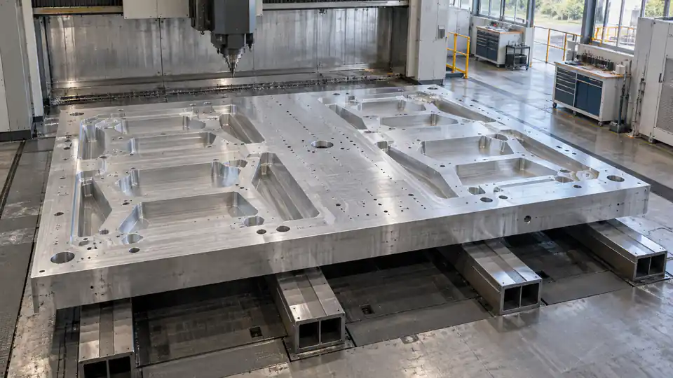
Large plates often look simple in CAD: two broad faces, pockets, hole patterns, and an outside profile. In production, the combination of stock flatness, residual stress, gravity, clamping, asymmetric removal, heat, and measurement support can move the part more than the drawing permits. A plate may be flat on the fixture and bowed after release.
This large aluminum plate machining design guide explains material condition, stress relief, roughing sequence, intermediate stabilization, workholding, thermal effects, and free-state inspection. It avoids universal flatness or stress-relief promises; the correct route depends on alloy, temper, thickness, span, removal pattern, tolerance, quantity, and final service.
Define What “Large Plate” Means for the Route
Size is relative to the machine and tolerance. A 600 mm plate may be routine on one machining center and require special handling on another. Risk increases when the part approaches table travel, has a high span-to-thickness ratio, retains little material, or requires tight flatness across a broad area.
Provide finished dimensions, stock size, mass, datum scheme, lifting needs, and tolerance zones. A supplier needs both geometry and allowable shape to choose the machine, fixture, and inspection setup.
Residual Stress Exists Before Machining
Rolling, quenching, stretching, leveling, forging, sawing, flame cutting, and prior machining leave internal stress. When material is removed, the remaining cross-section finds a new equilibrium and changes shape. The cutter does not have to “push” the plate visibly for distortion to occur.
Material certificates identify grade and condition but do not map stress in each blank. Product form, thickness, mill practice, location within parent stock, and lot can affect behavior.
Choose Material Condition Deliberately
Stress-relieved aluminum plate, cast tooling plate, normalized or stress-relieved steel, and prehardened products can reduce risk for some applications. They differ in strength, toughness, fatigue, corrosion, welding, anodizing, certification, and availability.
Do not replace the specified grade with a more stable machining product unless design authority approves every property and compliance difference. If dimensional stability is important, state the required product form and temper in the RFQ.
Start with Adequate Stock Allowance
The blank must cover mill thickness tolerance, bow, twist, saw damage, oxidation or scale, clamping, and cleanup on both faces. Choosing stock only slightly thicker than final can leave no material to correct low areas after relaxation.
Excessive allowance increases removal and can release more stress. The supplier should select a balanced amount tied to stock quality and process sequence.
Inspect Incoming Stock
Record material identity, heat or lot, dimensions, visible damage, and initial shape before machining. Support the blank consistently so measurements are comparable. For critical programs, map thickness and flatness or screen material using agreed criteria.
Incoming inspection does not predict all later movement, but it prevents a severely bowed or thin blank from entering an expensive route unnoticed.
Sawing and Profile Cutting Add Stress
Saw cuts can release parent-stock stress. Flame or plasma cutting adds a heat-affected zone and thermal distortion; waterjet avoids a large heat-affected zone but can leave taper and surface effects. Laser cutting has its own thermal and thickness limits.
Leave enough edge allowance to remove affected material where required. Allow the cut blank to stabilize before precision setup, especially after an asymmetric profile is separated from a large plate.
Rough Both Faces
Machining one face to final while the opposite retains mill skin and bulk material creates an unbalanced section. A common strategy faces or roughs both sides in stages, removing comparable layers where geometry allows. The plate is flipped, reclamped, and allowed to move before final datum establishment.
Balanced removal is a principle, not a fixed recipe. Deep pockets on one side may still dominate. The route should consider final mass distribution and stiffness.
Leave Uniform Finish Stock
Roughing should leave a controlled, reasonably uniform allowance on final faces, walls, and pockets. Heavy local stock makes the finishing tool remove different loads and can trigger new movement. Too little stock may not clean up after relaxation.
Record the intended allowance in the process plan and verify it at critical regions. Rest machining and semi-finishing can equalize stock before final passes.
Add an Intermediate Relaxation Stage
After roughing, remove the part from the fixture and allow it to reach a free state. Depending on material, size, tolerance, and validated practice, the route may include time at stable temperature, an approved thermal stress-relief cycle, vibration only when specifically qualified, or simply unclamped equilibration followed by reinspection.
Stress relief does not make a part permanently immune to later removal. It changes or reduces the current stress state. Subsequent asymmetric finishing, coating, or service temperature can still move the plate.
Thermal Stress Relief Requires Metallurgical Approval
Heating can reduce residual stress, but temperature and time can change temper, strength, hardness, microstructure, straightness, surface condition, and certification. Aluminum heat-treated tempers and hardened steels have restricted thermal histories.
Use a material-specific, approved process with controlled furnace records, load support, ramp, soak, and cooling. Do not apply a generic “stress relieve” note without temperature, specification, and final property requirements.
Natural Aging and Time
Some movement occurs promptly after unclamping; other changes may appear over hours or days through temperature equilibration, polymer behavior, or residual stress redistribution. Waiting is not a substitute for a qualified thermal process, but a defined stabilization time can improve repeatability before final inspection.
State the interval and environment for critical plates. An undefined “let it sit” step is difficult to schedule and audit.
Workholding on a Large Surface
Large plates need support against gravity and cutting load without being forced flat. Three primary support points define a plane, but additional adjustable supports may be needed under flexible regions. Those supports should contact without lifting or overconstraining the part.
Clamps should act near support points and direct the plate toward locators. Excessive edge clamping can bow the center; distributed vacuum can pull an already bowed plate into the fixture.
Vacuum Fixtures
Vacuum provides broad support and open top access. Holding force depends on pressure differential and effective sealed area. Pockets, holes, surface roughness, coolant, gasket condition, and leakage reduce capacity.
If the vacuum table flattens the work during finishing, the released part may recover its previous bow. Measure after release and include secondary supports or a relaxed intermediate setup when free-state flatness matters.
Magnetic Workholding
Magnetic chucks can hold ferromagnetic plates over a wide area. Pole pattern, part thickness, material, contact, surface condition, and cutting force affect grip. Residual magnetism and attraction of chips can matter for the product.
Like vacuum, a magnetic chuck can restrain the plate. Validate free-state results and demagnetization where needed.
Fixture Plate and Table Accuracy
A large machine table, tombstone, or tooling plate has its own flatness, contamination, thermal behavior, and wear. Chips or burrs under one support can tilt the work. A precise fixture on an unverified machine interface cannot guarantee the part.
Clean, inspect, and qualify support locations. Record machine and fixture revision for repeat work. Large fixtures also need lifting and storage practices that prevent damage.
Gravity Changes with Orientation
A thin plate sags differently horizontal, vertical, and supported at different points. Machining horizontal and inspecting vertical can produce apparent disagreement. The drawing’s free-state or restrained-state rules and the functional mounting condition should guide orientation.
For tight flatness, document support points and gravity direction during inspection. If assembly bolts the plate to a rigid frame, consider whether a controlled restrained requirement better represents function, while still limiting assembly force.
Datum Strategy
Choose datums that can be established after roughing and that represent assembly. A broad primary face with significant form error may create different alignments under physical supports and a CMM least-squares plane. Datum targets can define discrete contacts where appropriate.
Avoid locating critical hole patterns from a saw edge that is later removed or from a face forced flat only in the first setup. Preserve datum transfer through the route.
Pocketing and Rib Layout
Deep pockets remove stiffness and material asymmetrically. Ribs, bosses, and boundary flanges influence how stress redistributes. Rough pockets in a sequence that maintains support, and leave floors or webs thicker until major material is removed.
Design can improve stability with symmetric pockets, ribs along long spans, gradual transitions, and sufficient base thickness. An isolated heavy boss beside a thin field is a common distortion driver.
Through-Holes and Large Cutouts
Hole patterns and windows interrupt load paths. A large center cutout can release edge stress and turn a plate into a flexible frame. Consider roughing the opening while leaving tabs or a temporary web, then finishing after surrounding features stabilize.
Profile-cut blanks may save machine time but arrive already distorted. Compare total route and cleanup rather than only removal volume.
Long-Reach Tools and Heat
Deep pockets can force long tools, smaller engagement, and long cycle times. Heat accumulates in the spindle, tool, part, and fixture. Thermal growth can shift depth, position, and flatness during the final hours of a large program.
Use machine warmup, stable coolant, suitable tooling, balanced paths, probing, and a defined final temperature. Do not finish one side cold and the other after hours of heating without understanding the effect.
Roughing and Finishing on Different Machines
Roughing may use a high-power machine while finishing uses a more accurate or larger-travel machine. Transfer introduces new datum setup, support, temperature, and queue. It can be economical when each resource suits its task.
Qualify the transfer surfaces and allowances. Protect the partly machined plate during transport and allow it to stabilize before final alignment.
Five-Side and Five-Axis Machining
Five-axis or five-sided setups can reduce flips and preserve feature relationships, but a large flat plate still needs stable support. Rotary orientation changes gravity, and machine travels or payload can limit access. A one-setup claim does not eliminate stress release after unclamping.
Compare setup reduction with fixture restraint and tool reach. Final free-state inspection remains essential.
Grinding After Milling
Surface grinding can achieve flatness, parallelism, thickness, and texture on suitable materials, but it removes only accessible faces and can add heat or residual stress. Large grinder capacity and magnetic holding may constrain sourcing.
Plan milling allowance for grinding and specify the final datum and support condition. For aluminum, specialized grinding practice is required; not every surface grinder or wheel is appropriate.
Heat Treatment and Coating Sequence
Heat treatment after rough machining can move the plate and create scale or hardness changes. Anodizing, plating, paint bake, conversion coating, and other finishes add thermal or chemical exposure and thickness. Final dimensions may need allowance or post-process machining.
State which requirements apply before and after each process. Measure representative parts through the route to quantify movement instead of assuming coating is dimensionally neutral.
Free-State Flatness Inspection
Flatness is evaluated on the surface independent of a datum, but physical support and gravity affect a flexible plate. CMM, surface plate and indicator, laser, optical methods, and straightedges have different sampling and uncertainty.
Define support, orientation, temperature, point or scan density, filters, excluded regions, and final condition. A sparse point set can miss local shape; a best-fit display can hide peak-to-valley error.
Parallelism and Thickness
A plate can have constant thickness while both faces bow together, or good flatness on each face with incorrect parallel relationship. Thickness, flatness, and parallelism answer different questions. Specify only the controls needed for assembly and machining reference.
Measure thickness at defined locations and relate parallelism to the stated datum. Consider surface texture and burrs at contact points.
Large-Volume CMM and Alternative Metrology
A conventional CMM may not fit the plate or support it in the required orientation. Portable arms, laser trackers, scanners, autocollimators, interferometric methods, large surface plates, or qualified custom fixtures may be used. Each has different uncertainty and feature definition.
The RFQ should identify the required results, not mandate an instrument that cannot make them credibly. Ask the supplier to propose and document the method.
Packaging and Transport Can Reintroduce Distortion
A conforming plate can bend under straps, uneven dunnage, stacking, forklift handling, or temperature during shipment. Provide broad, defined supports; protect precision faces; prevent corrosion; and limit stacking or clamp load.
Include handling symbols and receiving instructions. If the part needs a shipping frame, treat it as controlled tooling and verify the part after removal during qualification.
Correlate the Machine, Fixture, and Inspection Supports
Three support layouts can produce three different shapes from the same compliant plate. During process qualification, measure a representative component on the machining supports after cutting, in the final inspection setup after release, and—when practical—on the assembly interface. The objective is not to make the numbers identical; it is to understand which shape each setup creates.
If the machine probe reports a surface as nominal but the free-state CMM rejects it, review restraint before editing cutter compensation. Compensating for a support-induced error can create the opposite error after the fixture changes. Keep support coordinates, jack or clamp settings, and orientation with the process record.
For repeat work, verify support pads before loading and use a seating check. A chip only 0.05 mm thick can be significant against a large flatness tolerance. Inspection should also confirm that dunnage, granite contacts, or fixture buttons have not worn into a new pattern.
Manage Rework Without Chasing the Plate
Re-machining a bowed plate is risky because removing material can release more stress and reduce thickness margin. Before rework, map actual thickness and shape in a known free-state setup, identify remaining stock, and simulate which surfaces will become datums. Engineering must confirm that final minimum wall and strength remain acceptable.
Do not clamp a rejected plate flat, skim it, release it, and repeat until the surface cleans up. That cycle can consume material without converging. A controlled rework may use localized support, symmetric material removal, an approved straightening or stress-relief operation, and a fresh final inspection.
Record every rework pass, heat cycle, straightening action, and new measurement. If the plate cannot be recovered without changing requirements, use a formal deviation decision rather than silently widening the acceptance method.
Quarantine the part between assessments so another operation does not consume the remaining allowance. Rework instructions should identify the exact surface, setup, maximum removal, required supports, intermediate checks, and final authority. After recovery, update the process risk review; repeated rework is evidence that the baseline route, stock condition, or tolerance allocation needs correction.
Preserve photographs and measurement maps with the serial or lot record so later teams can compare distortion direction, magnitude, and recovery across material heats.
A Route Comparison
| Route | Advantages | Main risks |
|---|---|---|
| Machine one side to finish, flip once | Short and simple | High asymmetric stress release |
| Balanced rough both sides, relax, finish | Better stability | More setups and calendar time |
| Stress-relieved/tooling plate | Lower starting-stress risk | Material/property constraints and cost |
| Rough, approved thermal relief, finish | Can reduce residual stress | Metallurgical change and extra lead time |
| Mill then grind critical faces | Strong final face control | Specialized capacity and holding effects |
| Near-net profile blank | Less removal | Cut-edge stress and initial distortion |
The correct route follows function, material, and evidence, not the fewest operations.
Cost Drivers
Large plates add raw-stock allowance, saw or profile cutting, heavy handling, large-machine rate, long roughing cycles, flips, fixtures, relaxation time, thermal processing, grinding, metrology, and protected shipping. Yield risk rises because failure occurs after substantial value has been added.
Request nonrecurring, per-batch, and per-part elements separately. Ask which tolerance or feature dominates each cost.
DFM Changes to Consider
- Increase base thickness or add ribs along unsupported spans.
- Balance pockets and mass removal across the neutral plane.
- Reduce unnecessary global flatness or parallelism.
- Define local mounting pads instead of one full precision face.
- Add datum targets matching assembly contacts.
- Permit larger internal radii and shorter tools.
- Standardize available plate thickness.
- Separate a monolithic plate into a qualified frame and panel when suitable.
- Provide handling and clamping regions outside critical surfaces.
- Define restrained-state performance when the assembly truly controls shape.
Verify structural, sealing, thermal, dynamic, and fatigue effects before changing the design.
What to Send for Quotation
Provide the 3D model, controlled drawing, material specification and condition, product form, finished and blank envelope, mass, quantities, flatness and parallelism zones, datum targets, pockets, final finish, heat or coating sequence, inspection state, and packaging.
Ask for a route showing incoming stock, roughing by side, remaining allowance, unclamping or relaxation, any heat treatment, final setups, inspection support, and shipping protection. This reveals whether two prices represent the same risk control.
Questions Before Award
- What stock condition and thickness allowance are assumed?
- How are both faces and deep pockets rough-machined in balance?
- When is the plate unclamped and allowed to move?
- Is thermal stress relief proposed, and how are properties protected?
- How do supports and clamps avoid forcing the part flat?
- What machine and fixture handle the full envelope and mass?
- How are temperature and long-cycle growth controlled?
- What final free-state support and measurement method are used?
- How do finishing and shipping affect the accepted shape?
- Which design change would reduce distortion or route time most?
Release Checklist
- Specify grade, temper, product form, and certification.
- Measure incoming dimensions and condition on controlled supports.
- Leave allowance for stock variation and relaxation.
- Balance material removal across faces and regions.
- Use uniform semi-finish stock before final cutting.
- Add an approved relaxation or stress-relief stage where justified.
- Re-establish functional datums after movement.
- Control supports, clamps, gravity orientation, and temperature.
- Inspect in the final free or defined restrained state.
- Account for coating, grinding, handling, and shipping.
- Trace process, fixture, machine, and material lot revisions.
- Validate the route across representative plates, not one result.
The Practical Manufacturing Decision
Large-plate accuracy is created by the entire sequence, not by the final finishing pass alone. Stable material, balanced roughing, unclamped relaxation, controlled datum re-establishment, appropriate final processing, and reproducible inspection all matter.
For a meaningful trial, record plate orientation, support locations, clamp sequence, roughing allowance, elapsed time before finishing, ambient temperature, and the free-state measurement after unclamping. Repeating those conditions on a second representative plate provides stronger process evidence than adding another finishing pass to a single favorable result.
The most economical route is the simplest one that produces the required free or assembled shape with evidence. To review a real plate, send the 3D model, controlled drawing, material condition, quantity, finishing sequence, and acceptance method through Request a Quote.
Retain the approved support and inspection state with every released result.