
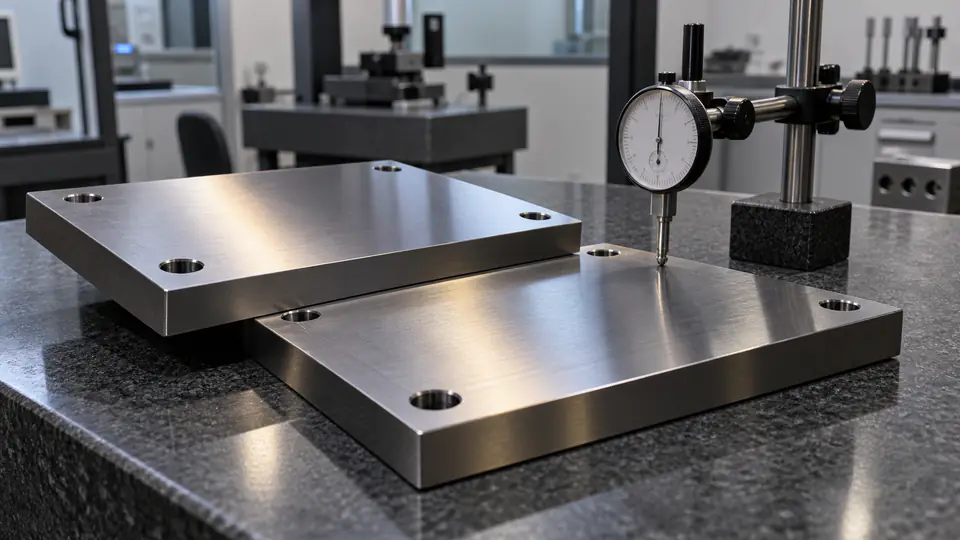
Flatness and parallelism are often placed together on CNC drawings, but they control different relationships. Flatness controls one surface independently of a datum. Parallelism orients a surface relative to a datum. Neither automatically controls thickness, surface texture, sealing performance, free-state distortion, or the behavior of an assembly under bolt load.
This flatness parallelism CNC machining guide explains how to choose the control that matches a mating interface, define the inspection state, design a stable machining route, and avoid specifications that are expensive but functionally incomplete. Interpret symbols and defaults through the drawing’s stated ASME Y14.5 or ISO 1101 edition and qualified GD&T review.
Understand the Flatness Tolerance Zone
Surface flatness creates a zone between two parallel planes separated by the tolerance value. All points of the actual surface must lie within that zone under the applicable standard. No datum reference is used because flatness is a form control.
Flatness does not locate or orient the surface to another feature. A face can be very flat yet tilted relative to the opposite face or mounting datum. It also does not state the distance between opposing surfaces.
Use flatness when the surface itself must avoid bow, twist, or local high and low regions regardless of its relationship to another feature. Typical examples include a plate resting on a base, a lapping reference, or one contributor to a sealing interface.
Understand Surface Parallelism
Surface parallelism creates a zone of parallel planes oriented to the referenced datum. The controlled surface must stay within that zone. Because the zone also limits the surface’s form, a parallelism requirement can indirectly restrict flatness to no more than the parallelism value under the governing rules.
Parallelism is appropriate when orientation to another plane, axis, or datum system matters: two mounting faces, guide surfaces, a cover relative to a base, or a bearing shoulder relative to an axis.
It does not by itself control the separation or thickness between surfaces. Add a size or location dimension where function requires it.
Compare the Requirements
| Product need | Likely control | Additional requirements to consider |
|---|---|---|
| One face must not rock on a plate | Flatness | Texture, contact area, free-state condition |
| Top face must remain parallel to mounting base | Parallelism to datum base | Thickness/height, flatness if independently tighter |
| Two faces define controlled thickness | Size plus applicable geometric controls | Local size, flatness, parallelism under selected standard |
| Gasket land must seal | Flatness or profile based on design | Texture, scratches, waviness, bolt pattern, assembled load |
| Slide or guide must track a base | Parallelism | Straightness, texture, wear, lubrication |
| Thin plate must fit after bolting | Defined mounted-state profile/flatness | Fixture, torque, sequence, free-state envelope |
Choose from function, not from the fact that the surfaces look rectangular in CAD.
Choose Functional Datums
A parallelism callout is only as meaningful as its datum. Select the feature that establishes orientation in assembly or use. A broad mounting surface may be a logical primary datum, but it must be sufficiently stable and accessible to simulate.
Avoid selecting a rough, flexible, interrupted, or nonfunctional face because it is easy to place at the bottom of a drawing. If the mating system contacts three pads rather than the entire surface, datum targets or a defined simulator may better represent constraint.
Document how the datum is established physically. Inspection software can construct a plane from many strategies; a least-squares fit is not always equivalent to a functional simulator.
Control Thickness Separately
Flatness of both faces does not guarantee a controlled thickness, and a thickness size tolerance alone may not prevent wedge or bow under all rules. Review how size and geometry interact in the chosen standard.
For a plate spacer, the design may need:
- thickness limits;
- flatness of the primary contact face;
- parallelism of the opposite face to that datum;
- local contact or profile control;
- surface texture;
- edge and burr limits.
Avoid redundant controls that create conflicting interpretations. A qualified GD&T review should establish which specification owns form, orientation, and size.
Define the Functional Contact Area
Not every portion of a nominally planar face may contact. Relief pockets, counterbores, slots, seal grooves, and edge breaks interrupt the surface. Identify the controlled region or multiple separate zones.
For three or more pads, decide whether each pad is flat, whether the pads are coplanar, and whether their common plane is parallel to another datum. A single whole-face flatness callout may not communicate that relationship.
Where only an annular sealing land matters, control that land rather than a recessed center. Mark start and end boundaries in the model or drawing.
Consider Bolted-Joint Behavior
Bolts pull surfaces together and can flatten a flexible plate locally. Sealing or thermal contact depends on stiffness, fastener spacing, preload, gasket or interface material, surface shape, texture, and pressure or thermal loads.
A free-state flatness requirement can improve assembly consistency but may not predict the final contact-pressure distribution. Conversely, accepting a severely bowed part only because bolts can force it flat can overload fasteners, distort mating hardware, or reduce fatigue life.
Use structural/contact analysis and representative tests for critical joints. Define both free-state and assembled requirements only when each supports a decision.
Define Free-State or Restrained Inspection
Thin plates and housings can move under gravity, probe force, support, vacuum chucking, or clamps. The drawing or inspection plan should state the condition.
For free-state measurement, define orientation and support points when gravity is material. Supports should avoid forcing the part into a result. For restrained measurement, define fixture or mating simulator, fastener locations, torque or clamp force, sequence, and temperature.
Do not permit an inspector to press a part flat by hand. An undocumented restraint makes results neither repeatable nor functionally interpretable.
Account for Temperature
Large plates and tight tolerances can change measurably with temperature. Temperature gradients can bend a part even when average temperature is near the reference. Machining heat, washing, sunlight, transport, and handling can create gradients.
Allow parts to stabilize before final measurement when necessary. Record material, measured temperature, reference temperature, and compensation method. Measure the fixture or surface plate environment as well as air.
For assemblies of different materials, analyze operating temperature. A room-temperature parallelism result may not represent a heated optical, semiconductor, battery, or automation system.
Select Stock and Material Condition
Residual stress in plate, rolled stock, castings, forgings, and heat-treated material can cause movement as surfaces are removed. Stock thickness and flatness also affect how much force is needed to hold the workpiece.
Specify alloy, temper, product form, and any required stress-relieved condition. Allow enough machining stock for cleanup without selecting an unnecessarily oversize blank.
For critical repeat production, track material source and lot performance. A certificate shows material identity; it does not prove residual-stress behavior. Use machining history and dimensional data to assess stability.
Balance Material Removal
Removing most material from one side of a plate can release stress asymmetrically. A balanced route roughs both sides, leaves controlled allowance, allows stabilization when appropriate, and finishes functional faces in a planned sequence.
The exact route depends on part geometry and shop capability. Buyers should ask how the supplier will manage distortion and inspect free-state geometry, not mandate a universal number of flips.
Designers can help with more uniform sections, fewer isolated heavy bosses, gradual transitions, and accessible clamping lands. A severe pocket pattern may require redesign rather than an unrealistically tight final flatness note.
Use Workholding That Does Not Hide the Error
Strong clamps can flatten a bowed blank. The machine then cuts a flat surface relative to the fixture, but the part springs after release. Vacuum tables can distribute force yet still deform thin material; magnetic or adhesive workholding has its own effects.
The supplier should minimize distortion while resisting cutting loads. Options include controlled support points, low-force clamping, soft jaws, sacrificial stock, balanced operations, vacuum-zone design, or bonded fixtures. Verify the final part after release.
Document any restraint used for acceptance separately from process clamping.
Choose Cutting and Finishing Methods
Face milling is efficient for many mating surfaces. Tool condition, insert height, spindle alignment, path, step-over, cutting force, and thermal state affect flatness and texture. Grinding can achieve fine geometry and finish on suitable materials but adds handling and datum-transfer considerations. Lapping can improve contact and flatness but removes material slowly and can alter thickness or edges.
Do not prescribe grinding or lapping solely from a tight value. Ask whether the required surface can be produced and measured in final material/finish condition at the given size.
For coated parts, determine whether finish machining occurs before or after treatment and whether exposed substrate is acceptable.
Separate Flatness from Surface Texture
A surface can be flat on a large scale and rough locally, or smooth but bowed. Specify texture with the applicable ASME B46.1 or ISO 21920 method when friction, sealing, thermal contact, appearance, or wear needs it.
Also consider waviness and lay. A face-milled spiral may meet Ra yet create a leakage path or visible pattern. A polished surface may have low roughness but long-wave shape that reduces contact.
Coordinate parameters and measurement filters so flatness data and texture data do not overlap or leave a gap unintentionally.
Measure on a Surface Plate
A surface plate with an indicator or height gage can provide a practical comparative flatness check for accessible parts. The method depends on support, cleanliness, instrument resolution, plate calibration, point spacing, and how the datum or reference is established.
Do not confuse rocking or a feeler-gage check with a complete flatness measurement unless the approved method defines it. Sparse points can miss local peaks and valleys. Record a grid or trace plan proportional to the surface and manufacturing pattern.
For parallelism, establish the datum surface appropriately and measure the controlled surface relative to it. A raw surface plate contact may not reproduce the datum simulator for an interrupted or flexible face.
Measure with a CMM
A CMM can sample surfaces and calculate flatness or parallelism, but results depend on point distribution, probe, datum alignment, fitting algorithm, filtering, and support. Use enough points or scans to detect the error wavelength expected from machining and part stiffness.
For flatness, do not overconstrain alignment to make the surface appear favorable. For parallelism, establish the referenced datum according to the drawing. Record actual range, method, and part condition.
Where different software filters or association methods could change acceptance, agree on them before production and correlate buyer and supplier results.
Use Optical Methods Carefully
Interferometry, laser scanning, structured light, autocollimation, or other optical methods may suit large, polished, complex, or noncontact measurements. Surface reflectivity, coating, curvature, line of sight, scale, and environmental vibration can influence results.
Qualify the method for the actual material, size, and tolerance. Temporary matte sprays or targets can change the surface and may be prohibited. Best-fit maps should not replace the drawing datum alignment.
Retain method, calibration, filters, uncertainty, and numeric extrema with any color map.
Plan Sampling and Capability
New, changed, or high-risk processes may need full layouts or 100% checks until stability is demonstrated. Mature repeat work may use sampled final inspection plus in-process controls. Define lot, sample selection, frequency, escalation, and reaction.
Capability data should come from a stable process using a measurement method whose variation is small enough for the decision. A few selected good parts do not establish capability. Review trends for bow direction, thermal shift, tool wear, and fixture effects.
Do not substitute machine specification for part capability across the actual size and route.
Correlate Supplier and Buyer Measurement
Measure the same identified parts at both locations. Control orientation, supports, stabilization time, cleaning, temperature, datum simulation, point grid, filters, and software. Share actual values rather than pass/fail alone.
If results disagree, preserve both datasets and investigate measurement conditions before changing machining. Flexible parts can move during transport or equilibrate differently, so record elapsed time and packaging restraint where relevant.
Approve the correlated method as part of the inspection plan.
Prepare a Quote-Ready Requirement
Include:
| Requirement field | Buyer definition |
|---|---|
| Functional surface | Marked face, pads, land, or region |
| Control | Flatness, parallelism, size, profile, or combination |
| Datum | Functional datum feature and simulator for parallelism |
| Tolerance | Value and governing GD&T standard/edition |
| Part state | Free, supported, restrained, assembled, temperature |
| Finish state | Before/after coating, grinding, lapping, or assembly |
| Texture | Parameter, lay, location, and measurement method |
| Inspection | Equipment, coverage, fitting/alignment, actual data |
| Sampling | First article, production frequency, reaction plan |
Ask the supplier to identify distortion, access, fixture, process, and measurement assumptions in the quote.
Common Failure Modes
Both faces are flat but the part is wedge-shaped
Flatness does not control their separation or orientation. Review thickness and parallelism requirements and inspect from the functional datum.
The part passes while clamped and fails free
Identify the drawing’s acceptance state. Remove undocumented restraint, contain product, and revise workholding or design. If mounted-state control is functional, define the fixture and also protect any needed free-state envelope.
Surface plate and CMM results disagree
Compare supports, datum simulation, point density, fitting, plate condition, temperature, and uncertainty. Inspect the same part under one agreed plan.
A fine Ra surface does not seal
Evaluate flatness, waviness, lay, scratches, gasket, bolt load, and mating face. Ra alone is not a sealing specification.
Flatness changes after anodizing
Review pretreatment, coating stress, material removal, racking, thermal exposure, and final-state requirement. Qualify the complete route.
Apply the Controls to Common Parts
Equipment base plate
The bottom interface may need flatness so the base sits without rocking, while the top rail pads need parallelism and height relative to that datum. If the machine frame contacts only discrete supports, define those areas rather than the entire underside. Review how anchor bolts and grout affect the installed condition. A shop-floor free-state result is only one contributor to machine alignment.
Valve or manifold cover
The sealing land may need flatness, texture, and a defect restriction. The opposite outer face may not need a close parallelism limit unless it locates another component. Internal pressure and bolt spacing can bend the cover, so validate gasket compression and proof-test distortion. Inspect after the final coating and any lapping step identified by the drawing.
Bearing housing split line
The joint faces can affect bore shape when the halves are assembled. Define whether faces are inspected individually and whether the bore is accepted with the joint torqued. Control dowels, fastener preload, surface finish, and any sealant. Tight individual flatness alone will not correct mismatched heights or incorrect assembly constraint.
Heat-sink or cold-plate interface
Thermal contact depends on the shape of the active footprint, interface material, mounting pressure, texture, and cleanliness. Mark the active area and check local waviness as well as overall flatness. A thin plate can deform during leak testing or cover joining, so use the final qualified state.
Linear-guide mounting rail
Parallelism and straightness relative to the machine base can influence motion. Define the datum and rail-pad zones, mounting sequence, and adjustment strategy. Do not force the machined casting to carry all alignment if the assembly intentionally uses shims or grout; document which geometry the component owns and which is set during commissioning.
Questions Buyers Often Ask
Should flatness be tighter than parallelism?
Not automatically. Surface parallelism can also constrain form within its zone, while a separate tighter flatness may be useful when local contact needs it. Select values from the tolerance stack and governing-standard interpretation. Redundant callouts can add inspection without changing the functional boundary.
Can a size tolerance control parallelism?
Size and form rules depend on the selected standard and feature definition, but a size alone is rarely the clearest way to establish a specific orientation relationship between functional surfaces. Use explicit GD&T when parallelism matters, then coordinate it with size to avoid conflicting or redundant limits.
How many points should be measured?
Enough to resolve the expected shape error across the functional zone. A large face with milling waves, thermal bow, or local clamp marks needs more than corner points. Use a documented grid or scan and increase density at transitions and known risks. Validate the plan on representative surfaces.
Is blueing or contact spotting an inspection method?
It can evaluate contact distribution in a defined lapping or assembly process, but it is not automatically equivalent to a numerical flatness tolerance. If used for acceptance, control the reference surface, contact medium, pressure, coverage criterion, operator method, and record. Keep geometric and contact requirements distinct.
Can the machine’s probing cycle certify flatness?
In-process probing can provide valuable control if its uncertainty, thermal state, probe calibration, fixture distortion, point pattern, and software calculation are suitable. It does not replace final free-state or post-finish inspection when later operations change the part. Correlate it with the accepted method before reducing final checks.
Retain the correlation data and repeat it after material, machine, fixture, probing software, or finish-process changes that could alter the result.
Final Design Checklist
Before release, verify that:
- flatness is used for independent form and parallelism for datum orientation;
- thickness or location is controlled separately where needed;
- datum features reproduce assembly constraint;
- contact zones, pads, and exclusions are marked;
- free or restrained state is explicit and reproducible;
- temperature and gravity orientation are addressed where material;
- stock form and residual-stress risk are considered;
- machining and workholding do not hide springback;
- texture, waviness, and geometric controls are separated;
- measurement coverage and software methods are agreed;
- supplier and buyer results are correlated for critical surfaces;
- sampling and reaction plans match product risk.
Specify the Relationship the Assembly Needs
A flat surface is not necessarily parallel, and a parallel surface does not automatically have the correct height or finish. Build the specification from contact, alignment, sealing, sliding, or thermal function, then define the state and measurement that reproduce it.
Send QuickCNCs the controlled 3D model and 2D drawing with functional datums, mating conditions, material, finish, quantities, and inspection needs. The team can review stable machining and measurement through CNC milling services and surface grinding services. Submit the complete package through Request a Quote.
References
- ASME Y14.5 Dimensioning and Tolerancing — GD&T rules for form and orientation controls.
- ISO 1101:2017 — geometrical tolerancing symbols and interpretation.
- ASME B46.1 Surface Texture — roughness, waviness, and lay specifications distinct from flatness.