
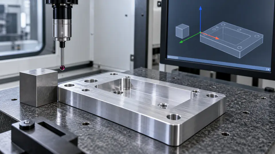
A clean-looking CAD model can be unusable for CNC release if its units, scale, origin, orientation, or coordinate frame are wrong. A 25.4× error is obvious once stock is ordered; a small origin shift or rotated datum may remain hidden until a fixture, CMM program, or mating part fails. The prevention is a short, repeatable validation performed on the actual files sent to the supplier.
This CAD unit scale check CNC guide explains how buyers and suppliers should verify units, extents, coordinates, bodies, transforms, and drawing consistency before quotation or programming. The focus is the product-definition handoff. It does not require every company to use the same CAD system or origin convention.
Treat Units, Scale, and Coordinates as Separate Checks
Units define how numeric values are interpreted, such as millimetres or inches. Scale compares the transferred geometry with intended physical size. Coordinates define where and how the geometry sits in a reference frame.
A file can pass one check and fail another. A STEP file can declare millimetres correctly but contain a body modeled at the wrong scale. A part can have the correct size but an origin 500 mm away. A drawing can show inch units while a DXF lacks explicit units and imports as millimetres. A rotated coordinate system can leave geometry correct yet invalidate a fixture or inspection program.
Verify all three explicitly.
Establish the Release Units
State the governing units on the drawing or model-based definition. Do not rely on regional convention, filename suffix, or CAD display settings. For dual-dimensioned drawings, identify the authoritative unit and rounding rule.
The RFQ manifest should list:
- source-model units;
- neutral-file units as encoded or exported;
- drawing units;
- any 2D profile or DXF units;
- tolerance units;
- mass-property units and density used;
- required output units for inspection reports.
If a format does not carry reliable unit metadata, include an explicit scale note and one or more reference dimensions.
Understand Why the 25.4 Error Persists
One inch equals 25.4 millimetres. When software imports a unitless value of 1 as 1 mm instead of 1 inch, the geometry becomes 25.4 times too small; the reverse becomes 25.4 times too large. The math is simple, but automated import defaults and manual overrides keep the failure common.
Do not “fix” an unknown file by scaling until the design authority confirms intended units. A model could be wrong for another reason, and rescaling might hide the source error. Record the correction and reissue a controlled file.
Use at least two independent reference sizes, preferably along different axes. A single familiar diameter can be misleading if that feature was modeled incorrectly.
Check Bounding-Box Extents
Bounding-box length, width, and height provide a fast scale and orientation check. Record them in the release manifest using the product units. Compare them after export and after supplier import.
| Validation property | Buyer export | Supplier import | Acceptance approach |
|---|---|---|---|
| X extent | Recorded value | Computed value | Match within agreed export/import tolerance |
| Y extent | Recorded value | Computed value | Match within agreed export/import tolerance |
| Z extent | Recorded value | Computed value | Match within agreed export/import tolerance |
| Solid-body count | Recorded integer | Imported integer | Exact unless difference is approved |
| Volume | Recorded with units | Computed with units | Compare using agreed precision |
| Surface area | Optional cross-check | Computed value | Investigate unexplained difference |
Extents do not prove full geometry. Two different parts can occupy the same box. Use them to catch gross errors quickly, then inspect functional features and validation properties.
Use STEP Validation Properties
NIST explains that validation properties are quantities computed by the native CAD system and stored to help validate import into another system. The receiving system can recompute the quantities and compare them with the originating values.
Where the authoring and receiving tools support them, use volume, surface area, centroid, or other encoded properties. Record the agreed comparison tolerance because different kernels and numerical precision may produce small differences.
NIST’s STEP File Analyzer and Viewer can report file information, PMI, and validation properties for supported STEP application protocols. It is a useful independent check, but the design and supplier teams still own the manufacturing release decision.
Define the Product Coordinate Frame
The product coordinate frame should support downstream use. It may align with functional datums, assembly coordinates, a machine concept, or the organization’s modeling convention. There is no universal origin that suits every part.
Document:
- origin location;
- positive X, Y, and Z directions;
- right-handed or applicable coordinate convention;
- named coordinate system in the source CAD;
- relationship to drawing datums;
- relationship to assembly or tooling frames;
- whether a supplier may transform the model for programming.
The supplier can choose machine work offsets and fixture coordinates. Those process frames should remain traceable to the released product frame and drawing datums.
Place the Origin Deliberately
A useful origin is stable across revisions and understandable to receiving systems. For a rotational part it may sit on the main axis at a functional face. For a prismatic part it may coincide with an intersection of datum planes. For an assembly interface it may use a mounting pattern center and primary face.
Avoid an arbitrary point far from the body unless the assembly context requires it. Large coordinate magnitudes can complicate viewing, numerical operations, and machine or inspection setup. Do not relocate an established released origin merely to make one setup convenient; use a process coordinate system instead.
If the origin changes between revisions, flag it explicitly even when geometry does not. CAM and CMM systems may interpret the model as a moved part.
Verify Axis Orientation and Handedness
Check the sign and direction of each axis using an asymmetric feature. A rectangular box cannot reveal a mirror if all faces look similar. Use a dowel hole, keyway, port, text mark, or controlled datum target to distinguish orientation.
For left-hand and right-hand parts, confirm that the release is a true intended mirror and that threads, countersinks, markings, and coordinate conventions change correctly. Assign distinct product identities.
Assembly exports can contain nested transforms. Open the neutral file in a second system and verify that child components remain in intended positions, not all at their local origins.
Compare the Model with the Drawing
Select a small set of high-information dimensions and relationships:
- overall size in three axes;
- primary bore or shaft diameter;
- distance between two functional features;
- thickness of a critical wall or flange;
- hole pattern orientation;
- origin-to-datum relationship;
- one asymmetric feature;
- one feature affected by the latest revision.
Measure them in the exported model and compare with the controlled drawing. If the drawing provides tolerances rather than exact model dimensions, use the nominal definition and authority rule.
Do not inspect only the thumbnail. A unit error can be hidden when the viewer automatically fits the model to the screen.
Check Every Body and Component
Part files can contain construction bodies, reference surfaces, alternate designs, or unmerged solids. Assembly files can omit or duplicate components through export selection.
Record intended solid and surface counts. Identify whether a multibody file represents one machined part, an assembly, inserts, stock, fixtures, or reference geometry. Remove or label nonproduct bodies before release.
For assemblies, compare component identities, quantities, and transforms. If the supplier needs only one manufactured component, send a part-specific file plus a clearly labeled interface assembly rather than leaving ordered scope ambiguous.
Validate 2D DXF and DWG Profiles
Two-dimensional formats often depend on import settings for units and scale. State whether the profile is model space at 1:1, which layer contains the cut geometry, and whether paper-space views or title blocks are included.
Check:
- units and 1:1 extents;
- closed contours and duplicate entities;
- spline, arc, and line continuity;
- layer names and intended operations;
- origin and material-side orientation;
- mirrored text or asymmetric features;
- whether line weight has any geometric meaning;
- a known reference dimension.
Do not derive a production profile from a plotted drawing view unless the release method specifically defines that geometry.
Check STL and Mesh Scaling
STL commonly carries triangle geometry without reliable unit metadata. State units in the manifest and filename, include reference dimensions, and verify extents after import. Mesh approximation also introduces chordal deviation; it is not equivalent to exact analytic CAD.
For CNC work, prefer a solid neutral format when available. If a mesh is the only source, define facet tolerance, intended use, surface quality, and whether reverse engineering or reconstruction is authorized. Do not let a supplier infer production dimensions from a coarse visualization mesh.
Control Tolerances and Precision During Export
Export translators use tolerances for sewing surfaces, approximating curves, and resolving topology. An overly loose setting can merge or distort small features; an extremely tight setting can create fragmented geometry or import difficulty.
Use validated company settings or supplier-agreed settings for the selected format and CAD pair. Record translator versions when the exchange is critical. Open the result and check for:
- open edges or failed solids;
- missing tiny faces;
- altered cylinders or cones;
- seam changes;
- duplicate surfaces;
- short edges and sliver faces;
- reported repair operations.
Do not confuse geometric tolerance in the translator with manufacturing tolerance on the drawing.
Include a Scale Reference Without Polluting the Model
A reference cube or ruler body can help with unitless visualization formats, but it can also be accidentally machined. For production solid models, prefer metadata, validation properties, and a manifest rather than adding nonproduct bodies.
If a reference object is necessary, place it in a clearly labeled separate file or layer and state that it is not part of the product. Confirm that CAM imports exclude it.
For 2D profiles, a dimensioned reference line outside the cut geometry can be useful if the file format and supplier workflow are agreed.
Validate Model-Based PMI
When PMI carries dimensions and tolerances, verify both semantic content and visual presentation in the receiving system. NIST distinguishes machine-interpretable semantic PMI from graphical presentation. A visible annotation is not proof that the downstream tool interpreted its meaning.
Check units for every PMI type, datum associations, tolerance values, saved views, and attachment to the intended geometry. Compare a report from the receiving system with the source authoring data.
If reliable semantic transfer is not established, supply a controlled 2D drawing or another approved human-readable definition for acceptance.
Handle Mixed-Unit Assemblies
CAD systems often manage inch and metric components correctly inside an assembly. Problems arise during export, custom automation, or downstream calculation. Verify component extents and transforms individually as well as the complete assembly.
Material density must use compatible mass and length units. A correct volume with an incorrect density unit can produce a plausible but wrong mass. Record the source of density values when mass or center of gravity is a product requirement.
For hardware libraries, confirm that nominal designations did not become numeric dimensions through an incorrect unit mapping.
Control the CAM Import
The supplier’s CAM system may automatically convert units, move the model to a setup origin, rotate it, or combine bodies. The programmer should preserve the untouched received file and create the manufacturing transform in a controlled job file.
Record:
- received-file checksum;
- detected units and any manual override;
- original extents and coordinates;
- applied translation and rotation;
- stock definition;
- selected product bodies;
- work-offset and fixture relationship;
- program revision.
If the model is rescaled or repaired, obtain engineering approval and keep the modified derivative under a new controlled identity.
Control the CMM and Inspection Import
Inspection software may also transform the model to a machine or fixture frame. Verify that the datum alignment reproduces the drawing and that nominal coordinates correspond to the released model.
A CMM program can produce credible-looking numbers against the wrong unit or state. Include a setup check using a known distance or artifact, confirm report units, and identify the program revision.
For large parts, temperature and material expansion may be material to scale. Define reference temperature or compensation as required by the drawing and metrology plan.
Build a Two-Party Preflight Record
Use a short acknowledgment before detailed programming:
| Check | Buyer release value | Supplier import value | Result |
|---|---|---|---|
| File and checksum | Controlled manifest | Received file | Match / investigate |
| Units | mm or in | Detected/imported | Match |
| Extents X/Y/Z | Recorded numbers | Recomputed numbers | Within agreement |
| Solid/body count | Intended count | Imported count | Match |
| Volume or area | Validation property | Recomputed | Within agreement |
| Origin and axes | Datum/coordinate description | Viewed orientation | Confirmed |
| Key dimensions | Selected nominal values | Measured import | Match |
| Translation warnings | None or listed | Import log | Closed |
This record is far cheaper than discovering the wrong scale after material, fixtures, or inspection programs are complete.
Automate Checks Without Removing Human Review
A release script can read file headers, compute hashes, extract units, count bodies, calculate extents and volume, and compare values with the PLM record. Automation is particularly helpful for batches of related parts because it applies the same tests consistently and can block a missing field.
The script itself needs configuration and version control. Validate it against known inch, metric, multibody, assembly, mirrored, and deliberately corrupted files. Record numerical tolerance and rounding. A tool that assumes every file is millimetres can make the release process look disciplined while repeating the same error automatically.
Keep a visual engineering check for orientation, handedness, intended bodies, and the latest design change. Numeric fingerprints cannot recognize every wrong feature, and a screenshot cannot validate encoded units. The strongest gate combines both.
If automation edits or heals the file, treat the output as a derivative requiring identity and review. A validation tool should not silently become a geometry-authoring tool.
Test a Known Reference Before a New CAD Pair
When a buyer and supplier use a new combination of authoring CAD, translator, and receiving CAM or CMM, exchange a controlled test part before a critical production model. Include simple analytic geometry, small features, multiple bodies, an asymmetric orientation marker, and representative PMI if needed.
Compare units, extents, volume, surface area, centers, cylinders, cones, splines, hole identities, and PMI at both ends. Record software versions and settings. The exercise reveals defaults and unsupported data while no production schedule is at risk.
Repeat qualification after major software or translator changes when the product risk justifies it. Successful transfer of one simple block does not prove every complex freeform part, but it establishes a known baseline and a communication path for discrepancies.
For recurring work, maintain a small regression set. Run it before accepting changed automation or export settings, then archive results with the change approval.
Train release and receiving personnel with real failure examples. Show the visual effect of a 25.4 scale error, a mirrored coordinate system, an assembly whose children collapsed to local origins, and a nominally successful import with an open shell. The objective is not software expertise for every buyer. It is recognition of a result that must be stopped and escalated before stock, fixtures, programs, or inspection records are built on it.
Include the preflight result in the job traveler or digital record so the approved import can be distinguished from later test copies. If the programmer receives a replacement file, invalidate the earlier check and repeat it. A successful validation belongs to specific file bytes, settings, and product revision; it is not a permanent approval of every file carrying a similar name.
That discipline keeps quoting, programming, machining, inspection, and repeat orders anchored to one verified physical definition.
Resolve Discrepancies Without Silent Repair
If validation fails, stop and classify the discrepancy. Determine whether the cause is source modeling, export settings, format limits, receiver import settings, unit override, or coordinate transform.
The design authority should decide whether to:
- correct and re-release the source;
- create a new verified neutral export;
- approve a documented receiver repair;
- select a different exchange format;
- provide additional drawing or PMI authority.
Retain the failed file and diagnostic record. Do not let a repaired copy circulate under the original filename and revision without approval.
Common Failure Modes
The model is exactly 25.4 times wrong
Confirm source units, encoded units, and import override. Re-export or re-import correctly and issue a controlled file; do not scale a production derivative silently.
The size is correct but all coordinates are far from zero
Check intended assembly context and product origin. If the distant origin is accidental, have engineering release a corrected frame. If intentional, use a documented process transform.
The drawing and model use different axis directions
Define the authoritative product frame and update views or exports. Verify handedness with an asymmetric feature.
CAM and CMM disagree after both imports pass
Compare transforms, datum alignment, units, source checksum, geometric repairs, and revision. Test both against the same reference dimensions.
A STEP file opens as surfaces
Review export schema, healing tolerance, open edges, and body selection. Do not assume a stitched surface is identical to the intended solid without validation.
Final Preflight Checklist
Before CNC release, verify that:
- governing units are explicit in the product definition and manifest;
- overall extents and key dimensions match the drawing;
- solid, surface, and component counts are intentional;
- volume, area, centroid, or other validation properties are compared where available;
- origin and positive axes are defined;
- handedness is proven with an asymmetric feature;
- assembly transforms and BOM identities are correct;
- DXF/DWG profiles are 1:1 with known units;
- mesh files include scale and facet information;
- export tolerances and translator versions are controlled where critical;
- PMI units and associations survive import;
- CAM and CMM transforms remain traceable to the released frame;
- discrepancies are corrected or formally approved, never hidden.
Make the Supplier Validate the Same Physical Part
Units, scale, and coordinates are simple data only when everyone interprets them the same way. A controlled preflight combines explicit metadata, numeric validation properties, visual orientation, drawing comparison, and a supplier acknowledgment on the received file.
Send QuickCNCs the verified 3D model and controlled 2D drawing with units, origin, revision, quantities, material, finish, and inspection requirements. The team can confirm import integrity and manufacturing orientation through CNC milling services and rapid prototyping. Submit the complete package through Request a Quote.
References
- NIST STEP File Analyzer and Viewer — STEP geometry, PMI, syntax, and validation-property analysis.
- NIST STEP at NIST — ISO 10303 and product-data interoperability context.
- NIST STEP File Analyzer User Guide — explanation of comparing geometric validation properties after exchange.