
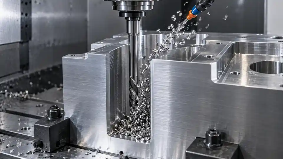
A deep milled pocket is not defined by depth alone. Its difficulty comes from the relationship between depth, opening width, internal corner radius, wall thickness, tool reach, holder clearance, chip escape, and the surfaces that must be finished or inspected. A broad 80 mm-deep cavity may be straightforward; a 30 mm-deep slot only 4 mm wide may require a long, flexible cutter and several special strategies.
The design question is therefore not “What is the maximum depth CNC can machine?” A useful review asks which tool and holder can reach every surface with acceptable stiffness, how chips and coolant leave the cavity, how much the walls move under cutting force, and how the final requirement will be measured.
This deep pocket CNC milling design decision guide gives engineers and buyers a way to evaluate those tradeoffs before quotation. It does not set universal depth ratios. Actual limits depend on material, machine, spindle, tooling, workholding, geometry, tolerance, finish, and quantity.
Define the Cavity in Section, Not Only in Plan View
Start with a section through the most restrictive path. Record:
- finished depth from the access face;
- minimum opening and local neck width;
- floor area and any steps or terraces;
- vertical corner radii;
- floor fillets and bottom geometry;
- draft, wall angle, or undercuts;
- remaining wall and floor thickness;
- nearby external geometry that blocks the holder;
- required surface texture and tolerance by zone;
- access for deburring, cleaning, and inspection.
A plan view can show a generous pocket while a shoulder near the opening prevents the tool holder from reaching the bottom. The cutter may fit; the collet nut, shrink-fit nose, arbor, or spindle head may not. Ask the supplier to evaluate the entire tool assembly against the 3D model.
Distinguish tool reach from cutting length
Overall reach, flute length, and stickout are different. A cutter may have enough overall length but insufficient flute length for the wall, or a long flute may reduce stiffness unnecessarily. The shank and holder need clearance from upper walls. Necked or relieved tools can reach around a restriction but are more flexible.
The process should minimize unsupported stickout. A long tool used only because the cavity is deep can chatter, taper, deflect, break, or leave an uneven surface. A stepped cavity that permits progressively longer tools can be much easier than a straight narrow shaft to full depth.
Use Depth-to-Width Ratio as a Screening Metric
Depth-to-width ratio is a quick indicator:
Pocket depth-to-width ratio = finished depth ÷ controlling pocket width.
For a slot, the controlling width may be close to cutter diameter. For an open cavity, use the local width that limits the holder or chip flow, not the largest opening elsewhere. For an irregular pocket, evaluate multiple sections.
The ratio is not a pass/fail rule. Two pockets with the same ratio can behave differently because of material, wall thickness, corner radius, opening, and finish. Use it to flag where a supplier needs a tool-access simulation and a detailed route.
Also calculate the expected tool length-to-diameter ratio for the smallest cutter that must reach the bottom. This is often more informative than pocket ratio. The design can reduce tool slenderness by increasing corner radius, opening a relief, splitting depth into levels, or allowing access from another side.
Internal Corner Radius Controls Cutter Diameter
A round end mill creates an internal vertical radius approximately related to its cutter radius, but using a cutter whose radius exactly equals the designed corner is poor practice. At the corner, engagement can jump toward full-width cutting, cutting forces rise, chip thickness changes, and the tool may dwell or chatter.
Provide clearance between cutter radius and part radius. A larger part radius lets the programmer use a larger, stiffer tool and maintain a smoother toolpath. The supplier can leave a controlled stock allowance and finish the corner with a smaller cutter only where necessary.
Separate vertical radius from floor fillet
The radius where two vertical walls meet is different from the fillet where a wall meets the floor. A square-end mill can create a flat floor and vertical-wall corner radius. A bull-nose or ball tool can create a floor fillet. If CAD uses one blended radius across several transitions, the cutter and path may not match the apparent geometry.
Dimension the functional requirement. If the mating part only needs clearance near the vertical corner, a dog-bone or localized relief may be better than forcing a tiny cutter through the full depth. Keep relief away from sealing and cosmetic zones.
Holder and Spindle Clearance
Tool-access review must include the holder taper, body, nose, collet, nut, extension, and spindle envelope. A tool can be long enough while the holder collides with an upper wall. Tilting a 5-axis tool may avoid the wall but create another collision or expose insufficient flute length.
Ask for a sectioned reach study showing:
- shortest tool assembly that reaches each depth;
- minimum holder-to-part clearance;
- required tool tilt or indexed orientation;
- cutter diameter and neck/flute length;
- fixture and clamp interference;
- inaccessible zones or rest material.
For a critical RFQ, a screenshot from CAM verification or a simplified reach envelope is more useful than “5-axis capable.” The QuickCNCs CNC milling services page describes machining capability, while the quoted route should identify the actual access solution.
Radial Engagement and Step-Down Strategy
Deep pockets should not be cut as one full-width plunge followed by heavy slotting. Modern roughing commonly uses controlled radial engagement, helical or ramp entry, and axial step-downs chosen for tool, material, machine, and chip evacuation.
Smaller radial engagement can reduce peak force and heat, permit deeper axial use of the flute, and maintain a more consistent load. It can also increase path length. The sustainable strategy depends on spindle power/torque, tool diameter, flute count, coolant, holder rigidity, and material.
Do not place feeds, speeds, or a mandatory toolpath on the drawing unless a qualified process is a design requirement. Define geometry and final acceptance, then ask the supplier how reach and load are controlled.
Roughing and finishing allowances
Roughing should leave a consistent allowance on walls and floor. An uneven rest condition causes the finishing tool to see changing engagement and deflection. Rest machining with successively smaller tools can remove corner stock without forcing the smallest cutter to rough the entire volume.
If walls are thin, roughing both sides or leaving temporary support can reduce movement. Finish features in a sequence that preserves stiffness. The quote should identify whether stabilization, unclamp/reclamp, or semi-finishing is needed before final cuts.
Chip Evacuation Is a Design Constraint
Chips must leave the cutting zone. In a deep blind pocket they can accumulate, recut, pack flutes, block coolant, damage the floor, or break the tool. The deeper and narrower the cavity, the harder it is for air, coolant, and chips to move.
Evaluate:
- upward chip path and cavity opening;
- horizontal ledges that trap chips;
- blind corners and intersecting pockets;
- tool flute volume and chip shape;
- through-spindle coolant or air availability;
- safe peck/retract or wash cycles;
- coolant drain and part orientation;
- cleaning and final debris verification.
A through hole or cleanout opening can transform chip evacuation, but it may not be functionally acceptable. If a temporary process hole is proposed, define plugging, sealing, appearance, and inspection before approval.
Material Changes the Feasible Route
Aluminum allows high material-removal rates but produces large chip volume. Long-reach tools can still chatter in corners or deflect against thin walls. Stainless steels generate heat and work-hardening risk; rubbing after deflection can damage tools and surfaces. Titanium combines heat concentration, cutting-force sensitivity, and tool-life concerns. Hardened steels may favor different tooling or a rough-soft/finish-hard route.
Engineering plastics can soften, smear, burr, or move with heat and moisture. Fiber-filled materials can be abrasive. Their lower stiffness can make thin walls deform under clamping and cutting even though cutting forces are lower than metal.
Specify exact material grade and condition. The QuickCNCs CNC machining materials page provides material context, but the supplier needs the released grade, temper or heat-treatment condition, and product form.
Wall Deflection and Dimensional Stability
Deep cavities often leave thin walls. As material is removed, stiffness falls. Cutting force pushes the wall away; when the tool passes, the wall springs back, leaving taper or excess stock. A finishing pass can repeat the deflection instead of correcting it.
Review:
- wall height-to-thickness and unsupported span;
- ribs, openings, and abrupt thickness changes;
- material modulus and residual stress;
- clamping location and force;
- roughing balance across opposite sides;
- tool approach direction and radial load;
- heat and coolant consistency;
- free-state versus restrained inspection.
Do not solve every concern with an unnecessarily tight wall-thickness tolerance. Improve stiffness where function permits, add generous transitions, balance material removal, and define the final measurement state.
Temporary support and sacrificial stock
The shop may leave a web, tab, boss, or thick floor during roughing and remove it later. This can stabilize walls and provide workholding. It adds operations and a final blend or cut surface. Confirm that removal does not damage cosmetic, sealing, or fatigue-sensitive areas.
For production, a dedicated support fixture or potting method may be justified. Ask about residue, cleaning, temperature, and compatibility before approving adhesives or fill materials.
Floor Flatness, Wall Straightness, and Surface Texture
Deep-pocket finishes are limited by access and stiffness. A long tool can produce wall taper, waviness, chatter marks, or steps between passes. Floor flatness can be affected by tool deflection, machine geometry, chip recutting, and thermal growth.
Specify finish only where function requires it. A blanket low-Ra note on every internal wall can add long finishing paths and inspection difficulty. Identify sealing, sliding, fluid, optical, or cosmetic zones separately.
If a pocket floor must be flat to a datum, define the datum relationship and measurement access. If a vertical wall requires perpendicularity or profile, consider how the inspector will sample the full depth. A probe stylus long enough to reach may also deflect or collide.
Inspection Access
A machinable feature is not automatically measurable with the intended method. Deep pockets block line-of-sight and restrict probe, bore gage, air gage, optical, or profilometer access.
Ask these questions during DFM:
- Can a CMM stylus reach the floor and lower walls without collision?
- Is enough stylus length available with acceptable stiffness?
- Can the probe sample the feature at the required depth and orientation?
- Can surface texture equipment access the controlled zone?
- Is a replica, special gage, borescope, or sectional method required?
- Does the inspection setup use the same functional datums?
- Is the requirement better verified functionally?
The QuickCNCs quality assurance page describes inspection resources. The drawing should still define an accessible, technically appropriate acceptance requirement.
Alternative Manufacturing Routes
Indexed or simultaneous 5-axis milling
Tool tilt can improve holder clearance, shorten effective reach, and access walls from better directions. It does not eliminate the need for adequate radii, chip evacuation, fixture clearance, and simulation. Machine travel and rotary envelope may limit large parts.
Split the part and assemble
Dividing a deep closed cavity into a base and cover can make both parts shallow. This adds fasteners, dowels, seals, tolerance stack, leak paths, cleaning interfaces, and assembly. Evaluate total function and lifecycle.
EDM
Sinker EDM can create deep blind features, sharp details, and hard-material geometry that is difficult to mill. It requires electrodes, suitable conductive material, flushing, burn time, recast/surface considerations, and inspection. Wire EDM needs a through path and cannot create a blind cavity by itself.
Drill, bore, broach, or turn
If the cavity is axisymmetric, turning or boring may be more stable than milling. Long narrow square features may support broaching in certain quantities. Deep holes may need dedicated drilling rather than an end mill.
Near-net construction
Casting, forging, additive manufacturing, extrusion, or welded construction can reduce removal. Each route introduces tooling, minimum quantity, allowances, material properties, qualification, and finish machining. Compare total delivered risk and cost.
Deep-Pocket Design Tradeoff Table
| Design variable | Easier-to-machine direction | Functional issue to recheck |
|---|---|---|
| Opening width | Wider access | Envelope, shielding, fluid path |
| Vertical corner radius | Larger radius | Mating-part clearance and local function |
| Floor fillet | Compatible with standard bull/end geometry | Seating or cleanout at floor-wall junction |
| Pocket depth | Shallower or stepped | Required internal volume and component clearance |
| Wall thickness | Thicker, shorter unsupported span | Weight, thermal response, package size |
| Access direction | Multiple open sides | Sealing, stiffness, assembly, appearance |
| Surface texture | Limited to functional zones | Flow, sealing, wear, cleaning |
| Tolerance | Functional, datum-based limits | Assembly and performance margin |
| Part architecture | Split or near-net | Joint, leak, tolerance stack, qualification |
Use the table to generate controlled alternatives, not automatic design rules.
Quote Cost Drivers
Deep pockets affect price through:
- CAM programming and collision simulation;
- long-reach or relieved tooling;
- special holders and reduced-clearance assemblies;
- slower sustainable cutting parameters;
- multiple roughing/rest-machining tools;
- chip-clearing cycles and operator attention;
- tool wear and breakage risk;
- multi-axis machine time;
- stabilization and additional setups;
- long-stylus or special-gage inspection;
- deburring and cleaning of inaccessible areas;
- scrap exposure late in the route.
Ask each bidder to identify the dominant constraint and proposed tool-access class. The supplier need not provide proprietary feeds and speeds. It should state which geometry drives special tooling, extra setup, slower cycle, or added inspection.
Review Different Cavity Types Separately
Open pocket with one accessible side
An open side can improve chip flow and let a cutter enter without plunging, but it may reduce part stiffness or create a burr at breakout. Confirm whether the open edge is functional, cosmetic, or later closed by another component. A process tab can temporarily close or support the edge and be removed after finishing.
Closed rectangular cavity
A closed cavity concentrates the vertical-radius and holder-clearance problem. The smallest corner may control the tool even when most of the volume is broad. Consider increasing only the nonfunctional corner radius, adding a relief, or allowing a larger roughing radius with localized rest machining. Define the bottom corners separately.
Narrow deep slot
A slot restricts cutter diameter, chip escape, and coolant access over its entire length. A slitting saw, side milling, wire EDM, assembled construction, or change in slot termination may be more robust than a long end mill. If the slot is blind, show its end shape and usable depth rather than implying a perfectly square end that the process cannot create.
Circular or axisymmetric cavity
Boring, turning, trepanning, drilling, or interpolation may provide a stiffer route than general pocket milling. Identify whether the floor must be flat, conical, spherical, or relieved. For a deep bore, control straightness, cylindricity, and surface texture only as function requires, and plan how they will be measured.
Fluid manifold cavity
Ports, pockets, and cross holes create burr and cleaning risks at intersections. Show the flow path, sealing faces, plugged openings, pressure boundary, and cleanliness requirement. Provide a way to see, reach, or verify the intersections. A cavity that can be machined but not cleaned or leak-tested is not production-ready.
Coolant, Air, and Fluid-Trap Considerations
Coolant delivery can control tool life and chip evacuation, but a deep pocket can trap fluid after machining. If the component enters vacuum, medical, optical, semiconductor, or clean service, define the allowed residue and drying condition. Blind holes, overlapping passages, and capillary gaps can retain liquid after a normal wash.
Review drain orientation and whether temporary handling positions are allowed. Consider adding a drain or access feature only when function permits. Do not specify “no coolant” as a general cure; dry or minimum-quantity machining may be unsuitable for the material and toolpath. Define the final cleanliness result and let the supplier propose a controlled process.
For pressure-containing parts, distinguish a machining coolant path from the final sealed circuit. Threaded plugs, press-fit balls, welded closures, or bonded covers introduce their own material, assembly, leak-test, and traceability requirements.
Use a Staged Approval for High-Risk Geometry
When the cavity is near a practical access or stability boundary, separate quotation, first-piece approval, and production release. At quotation, require the proposed tool/holder envelope and inspection concept. Before cutting production material, approve any DFM relief, process opening, or sacrificial feature. At first article, review dimensional data, wall condition, surface evidence, cleaning, and any tool-access witness marks.
Retain the qualified program revision, fixture/soft-jaw identity, critical tool assembly, and inspection setup for repeat orders. If the tool, holder, machine, stock form, or cavity geometry changes, determine whether the reach and stability review must be repeated.
This staged approach does not guarantee success; it places decisions before the points where failure becomes expensive. It is especially useful when a late deep feature could scrap a part that already carries substantial machining or finishing value.
RFQ Checklist for Deep Pockets
Before sending the RFQ, confirm:
- The 3D model and 2D drawing carry the same revision.
- Pocket depth, local opening, steps, and undercuts are explicit.
- Vertical corner radii and floor fillets are distinguished.
- Holder and spindle access has been considered, not only cutter diameter.
- Thin walls and floors are identified with functional tolerances.
- Material grade, condition, and product form are stated.
- Roughness applies only to required surfaces.
- Datums support machining and final inspection.
- Burr, chip, cleaning, and trapped-fluid requirements are defined.
- Coating, heat treatment, and dimensional state are clear.
- Inspection tools can reach the controlled surfaces.
- Alternate access, relief, split construction, or EDM may be proposed subject to approval.
- Prototype, batch, and annual quantity are provided.
- The supplier must identify assumptions, inaccessible areas, and DFM requests.
Ask for a Tool-Access and Verification Proposal
Send the native or neutral model, controlled drawing, material, quantity, finishing, inspection, and delivery needs. For the restrictive cavity, ask the supplier to show a sectioned access review, likely setup, tool class, rest-machining boundary, and inspection method.
For prototypes and low volume, flexible tooling may be more economical than a dedicated fixture; see the QuickCNCs low-volume CNC machining page. To request a part-specific review, submit the controlled files through the Request a Quote page.
A successful deep pocket is designed as a complete access problem. Give the cutter and holder room, use radii that support a stiff tool, provide a chip path, preserve wall stiffness, specify only necessary finish and tolerance, and make the final surfaces inspectable. That is how a deep cavity becomes a comparable manufacturing decision rather than a vague machine-capability claim.