
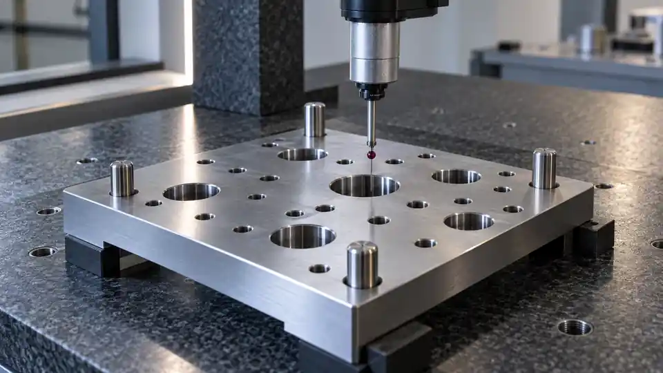
Position tolerance—often called “true position” in everyday manufacturing—controls where a feature of size may be located relative to theoretically exact dimensions and a datum reference frame. For bolt-hole and dowel patterns, it can express assembly function more accurately than separate plus/minus X and Y tolerances. It can also be misapplied. An incomplete datum scheme, missing basic dimensions, unintended material-condition modifier, or unsuitable inspection method can make the requirement ambiguous or unnecessarily expensive.
A CNC buyer does not need to program the machine or CMM, but should understand the release boundary. The drawing must define what locates the pattern, whether the holes are clearance or locating features, how feature size interacts with location, and how acceptance will be demonstrated.
This guide explains the decision. The exact interpretation of a drawing depends on the specified edition of the governing standard and the complete product definition. ASME Y14.5 is a primary reference for GD&T in many US supply chains; do not mix conventions from different standards without a controlled engineering decision.
What Position Tolerance Controls
For a cylindrical hole, a position tolerance normally creates a cylindrical tolerance zone. The derived axis of the actual hole must lie within that zone relative to the stated basic location and referenced datums, subject to any material-condition modifiers.
This differs from giving separate ± tolerances to X and Y coordinates. A rectangular coordinate tolerance creates a square acceptance region, while a diametrical position zone is circular in cross-section. The position callout also connects location and orientation to a datum reference frame and can define the pattern as a group.
Position does not automatically control everything about the hole. The size dimension controls diameter. Form is governed by the size limits and applicable rules of the selected standard unless separately controlled. Surface texture, perpendicularity nuances, thread quality, depth, and counterbore relationship may need additional requirements.
“True” is the basic location
The theoretically exact location comes from basic dimensions—boxed dimensions under ASME practice. Basic dimensions have no direct ± tolerance. The feature control frame supplies the allowable variation. Treating basic dimensions as if they also carry a title-block tolerance double-tolerances or contradicts the definition.
For a polar bolt circle, the basic bolt-circle diameter and basic angular spacing establish nominal locations. For a rectangular dowel pattern, basic X and Y coordinates do the same. The datum reference frame determines where that theoretical pattern exists on the real part.
Start with Assembly Function
Before choosing a position value, identify what the pattern does.
Clearance bolt holes allow fasteners to pass through and clamp two parts. Their location tolerance interacts with fastener size, hole size, mating-pattern error, and assembly clearance. The holes may tolerate more positional variation as actual diameter grows.
Tapped holes receive fasteners and often pair with clearance holes in a mating part. Threaded-hole location may be evaluated from the pitch-diameter axis, and projected tolerance may matter when a long fastener must pass through a thick mating part.
Dowel holes locate components and frequently need much tighter relationship to mating features. Size, fit, position, roundness, straightness, and the spacing between dowels can influence assembly. Two tight dowels can overconstrain a joint; designs sometimes use one round pin and one relieved/diamond pin to manage tolerances.
Bearing, bushing, or precision bores may use position, but coaxiality, perpendicularity, runout, profile, or a common-datum strategy can be more relevant depending on function.
The tolerance should protect the assembly requirement. Do not copy a value from a nearby hole with a different job.
Build the Datum Reference Frame
A datum reference frame establishes the coordinate system for evaluation. A common planar part uses a primary face to orient the part, a secondary edge or hole to remove additional movement, and a tertiary feature to complete location. A housing may use a mounting plane, a locating bore axis, and a clocking feature.
Choose datums that reflect how the part functions and can be simulated repeatably. The primary datum feature should be sufficiently stable and accessible. The secondary and tertiary datums should represent actual mating or locating interfaces. A small flexible tab selected only because it is convenient to dimension can create inconsistent inspection.
Datum order matters
The sequence A|B|C is not interchangeable with B|A|C. The first datum establishes the primary constraint; later datums remove remaining degrees of freedom. Changing the order can change the measured result even when the same features are named.
Walk through physical setup. How will the part contact the primary datum simulator? How will the secondary feature locate it? Where is the clocking constraint? Is the part measured free-state or restrained? If two inspectors can establish different frames from the callout, fix the drawing.
Datum features of size and mobility
When a datum feature of size is referenced with a material-boundary modifier, the datum simulator may permit datum shift or mobility as allowed by the standard and actual feature size. This can increase functional acceptance but also complicates software evaluation and gage design.
Do not add a modifier solely to obtain more tolerance. Use it when it represents the mating boundary. Confirm that the CMM program or functional gage applies the correct simulator and sequence.
Basic Dimensions Must Completely Locate the Pattern
The feature control frame cannot replace the nominal layout. Provide enough basic dimensions to define:
- the position of the pattern from the datums;
- spacing between pattern members;
- bolt-circle diameter and angular orientation where applicable;
- pattern orientation relative to the datum frame;
- any unequal spacing or clocking requirement;
- relationship between holes, counterbores, spotfaces, or related features.
Avoid duplicate basic schemes. Do not locate a hole once from an edge and again from another hole if both are intended to control the same degree of freedom. Use reference dimensions where a convenience value is needed but not independently controlled.
Check CAD and drawing consistency. The model should place the hole axes at the same basic coordinates shown on the drawing. If a STEP translation changes model origin but not geometry, the drawing-based datum frame still controls; the shop should not infer basic locations from an arbitrary import coordinate system.
RFS, MMC, and LMC on the Controlled Feature
Under ASME practice, a position tolerance applied to a feature of size without a material-condition modifier is regardless of feature size (RFS). The stated position value applies regardless of the actual hole diameter within its size limits.
At maximum material condition (MMC), the position tolerance applies when the hole is at its smallest permitted diameter. As the actual hole gets larger, bonus tolerance becomes available. This often matches clearance-hole assembly because a larger hole provides more room for positional variation.
For an internal feature such as a hole:
Bonus tolerance = actual hole size − hole MMC size.
Total available position tolerance = stated MMC position tolerance + bonus tolerance.
The calculation is only meaningful with the correct standard rules, units, and actual feature size. It does not mean the programmer can intentionally move the hole; the target remains basic position.
LMC may be used when minimum remaining wall thickness or another least-material boundary is the function. It is less common for ordinary clearance-hole patterns and should be applied intentionally.
Virtual condition and assembly boundary
For an internal feature controlled at MMC, the virtual condition is commonly understood as the hole MMC size minus the stated position tolerance at MMC. It represents a constant worst-case boundary for the feature under that control. A fixed functional gage pin can model this boundary when the complete datum and pattern design supports it.
Do not calculate a virtual condition in isolation. Mating fastener, mating pattern, datum mobility, projected zone, and applicable standard rules all influence assembly analysis.
Clearance Holes Versus Dowel Holes
| Design question | Clearance bolt-hole pattern | Dowel locating pattern |
|---|---|---|
| Primary function | Fastener passage and clamp load | Repeatable part location |
| Size/location interaction | MMC and bonus tolerance often align with clearance | Fit and location both tight; bonus may or may not represent function |
| Datum strategy | Mounting face plus assembly locators | Often uses one bore/pin as datum and another for clocking |
| Inspection | CMM or functional gage may be efficient | CMM, precision pins, functional nest, and fit verification may be needed |
| Common risk | Pattern passes on one part but mismatches mating pattern | Two pins overconstrain or spacing consumes assembly allowance |
| Buyer input | Fastener, mating-hole size, stack, assembly condition | Pin size/fit, mating part, insertion, thermal and service condition |
The table is a design-review prompt. Actual tolerance values require a stack based on mating geometry and function.
Composite Position for Pattern Control
A composite position tolerance can control two related aspects: the pattern’s location/orientation to the datum reference frame and the tighter relationship among features within the pattern. It is useful when the entire bolt pattern may “float” slightly on the part while hole-to-hole spacing must remain tight for a mating component.
The upper segment commonly controls the pattern relative to the referenced datums. The lower segment refines feature-to-feature orientation and location, with datum references governed by the standard and callout. This is not the same as placing two unrelated single-segment position controls on the hole.
Composite callouts are often misinterpreted. Before release, have the designer and inspector explain what each segment permits. Verify that the CMM software evaluates the pattern with the intended simultaneous or separate requirements. If the function can be expressed more clearly with another scheme, use clarity over complexity.
Projected Tolerance Zone for Threaded Features
A tapped hole can meet position at the part surface yet cause a long screw or stud to interfere with the mating clearance hole because angular error grows with distance. A projected tolerance zone extends the positional requirement above the surface through a stated height, representing the mating thickness or engagement condition.
Use a projected zone when the protruding fastener relationship justifies it. Define the projected height and drawing representation correctly. Provide the mating part thickness, clearance, and fastener information during DFM.
Inspection may require a projected pin, functional gage, or CMM construction that evaluates the axis over the required height. A short measurement of the thread entrance is not enough to prove the projected boundary.
Pattern Requirements and Simultaneous Evaluation
Several features controlled by one callout are generally evaluated as a pattern under the relevant rules. Separate callouts can create separate pattern requirements. The distinction affects whether the group may translate or rotate together and how datum mobility applies.
If two coaxial holes on opposite walls form one functional passage, make their relationship explicit. If a counterbore must be centered to a hole, control that relationship rather than assuming both locations from basic dimensions will guarantee concentricity.
The supplier should know whether all holes must be evaluated in one setup and whether the mating envelope is the acceptance basis. A report of individual X and Y deviations without pattern evaluation may not demonstrate conformance.
Manufacturing Strategy for CNC Hole Patterns
Position capability depends on how the datum frame is transferred to machining. A pattern created in the same setup as its datum features can avoid a manual transfer. Multiple faces may be indexed on a 3+2 or 5-axis machine. A second operation may locate from finished datum surfaces using soft jaws, pins, a fixture, or probing.
Process variables include:
- workholding repeatability and part distortion;
- drill walking on angled or rough surfaces;
- tool runout and hole-size control;
- boring, reaming, interpolation, or jig grinding for precision holes;
- thermal growth of part and machine;
- burrs at entry, exit, or intersecting holes;
- heat treatment or coating after machining;
- coordinate recovery between setups.
A tight callout may increase programming, fixture, probing, and first-article inspection. Ask for the proposed setup/datum strategy, not a generic machine accuracy number.
The QuickCNCs 5-axis CNC machining page is relevant when multiple faces or angled holes must remain in one coordinate system. A simpler machine can still be the right choice when reliable datum transfer meets the requirement.
Inspecting Position with a CMM
A CMM can establish the datum reference frame, measure feature size, derive axes or centers, and evaluate position. The result depends on the measurement strategy.
Review:
- datum feature sampling and mathematical construction;
- alignment sequence and material-boundary simulation;
- number and distribution of points in each hole;
- measurement depth and axis length;
- filtering and outlier treatment;
- actual feature-size method;
- temperature and part restraint;
- software support for composite, projected, and pattern rules;
- reporting of stated, bonus, and total tolerance.
A CMM printout that lists “true position” values without datum alignment, units, feature size, and callout context is incomplete. The QuickCNCs quality-assurance page describes inspection capability, but the RFQ must identify the specific report and acceptance method.
Diameter versus radial error
For a simple 2D position calculation from coordinate deviations, the diametrical result is commonly calculated as two times the radial distance:
Position diameter = 2 × √(ΔX² + ΔY²).
This shortcut does not replace a complete 3D datum-aligned evaluation. It may omit axis orientation, projected zone, datum shift, composite pattern behavior, and actual-size effects. Use it only for an appropriate simple check.
Functional Gaging
A fixed gage can simulate the worst-case assembly boundary for an MMC-controlled pattern. The part locates on datum simulators and pins represent the controlled hole boundaries. If the part seats and the pins enter under the specified conditions, the gage can provide efficient attribute acceptance.
Functional gages are valuable for production but need design, manufacture, calibration, wear control, identification, and handling. They usually provide pass/fail information rather than actual coordinate data. A gage that does not correctly simulate datum sequence, material boundaries, and all pattern members can accept or reject parts incorrectly.
For prototypes, CMM measurement may be more flexible. For stable volume, a qualified gage can shorten cycle time. The inspection plan can combine gaging for release with periodic variable data for process control.
Coating, Heat Treatment, and Final Condition
Define whether hole size and position apply before or after coating, heat treatment, or insert installation. Anodize or plating changes hole size and can affect the available bonus tolerance. Masking can preserve a fit but creates a finish boundary. Heat treatment can move the pattern relative to datums.
If a bushing or threaded insert establishes the final functional hole, decide whether position applies to the machined parent hole, the installed component, or both. State the installation and inspection sequence.
Final acceptance should represent the assembly condition. Do not use pre-finish measurements as the only evidence when later processing can change the controlled boundary.
Use Mating-Part Data in the Tolerance Review
A position callout cannot be optimized responsibly from one component alone. Provide the mating drawing or a controlled interface summary showing fastener or pin size, mating-hole size, engagement length, joint float, and which component establishes final location. Include the assembly sequence and operating temperature when they affect fit.
For a clearance-fastener joint, the tolerance stack should allocate available clearance between both patterns, feature sizes, datum relationships, and any assembly shift. For a dowel joint, review pin-size tolerance, bore fit, center distance, insertion method, and whether one locator needs relief. If only one component receives all available position tolerance, the mating part may become unnecessarily expensive or assembly may still fail.
Also identify whether parts from different suppliers must assemble interchangeably. A matched-pair process can make one assembly fit while preventing service replacement. If interchangeability is required, control each component to the common functional boundary and avoid undocumented selective assembly.
Ask suppliers to comment on the interface, but keep tolerance authority with engineering. A shop may identify that a larger clearance hole, relieved dowel, or changed datum would reduce risk; the controlled design must approve the proposal before the quote baseline changes.
Common Drawing Errors
Missing or redundant basic dimensions
The pattern is not fully located, or it is located twice by conflicting schemes. Correct the nominal definition before quoting.
Unstable or nonfunctional datums
The drawing references a small, rough, flexible, or inaccessible surface that does not represent assembly. Select datums from function and verify they can be simulated.
MMC added without a fit analysis
Bonus tolerance is assumed to reduce cost, but the constant boundary does not match the mating condition. Perform the assembly stack first.
Position used for a surface
Position applies to features of size and certain related constructs, not an arbitrary contoured surface. Profile is often the appropriate control for surface geometry.
Thread position without axis definition or projection
The evaluation method for a threaded feature is unclear, or long fastener engagement is ignored. Define the thread requirement, axis basis, and projected zone where functional.
Inspection reports only coordinate deviations
X and Y values are listed without the diametrical position result, datum frame, bonus, or pattern evaluation. Require a report tied to the complete callout.
RFQ Checklist for Hole-Pattern Position
Before sending the RFQ, confirm:
- Hole function is identified: clearance, threaded, dowel, bushing, or precision bore.
- Hole size, fit, depth, and secondary features are complete.
- Basic dimensions fully locate and orient the pattern.
- The datum reference frame matches assembly and can be simulated.
- Datum order and any material-boundary modifiers are intentional.
- RFS, MMC, or LMC on the controlled feature represents function.
- Mating fastener, pin, and hole sizes support the tolerance stack.
- Composite control is explained and supported by inspection.
- Projected tolerance zone is used where long fastener engagement needs it.
- Coaxial, counterbore, or cross-face relationships are explicit.
- Pre- and post-coating or heat-treatment conditions are defined.
- CMM and/or functional-gage method is agreed.
- Reports show units, datums, actual size, bonus, result, limit, and disposition.
- Quantity and release cadence support the proposed inspection method.
Make the Position Callout Quote-Ready
A true position hole pattern CNC decision guide should lead to one result: the supplier can understand the functional boundary, propose a capable route, and demonstrate acceptance without guessing. Send the controlled 3D model and drawing, mating-interface information, quantity, material, finishing, and inspection requirements.
QuickCNCs can review the datum and setup implications across prototype and production CNC machining. To request a process and inspection proposal, submit the controlled package through the Request a Quote page.
The strongest position requirement is not the smallest number. It is the requirement that represents assembly, uses a stable datum frame, states material-condition behavior intentionally, and can be verified with an agreed method in the final part condition.