
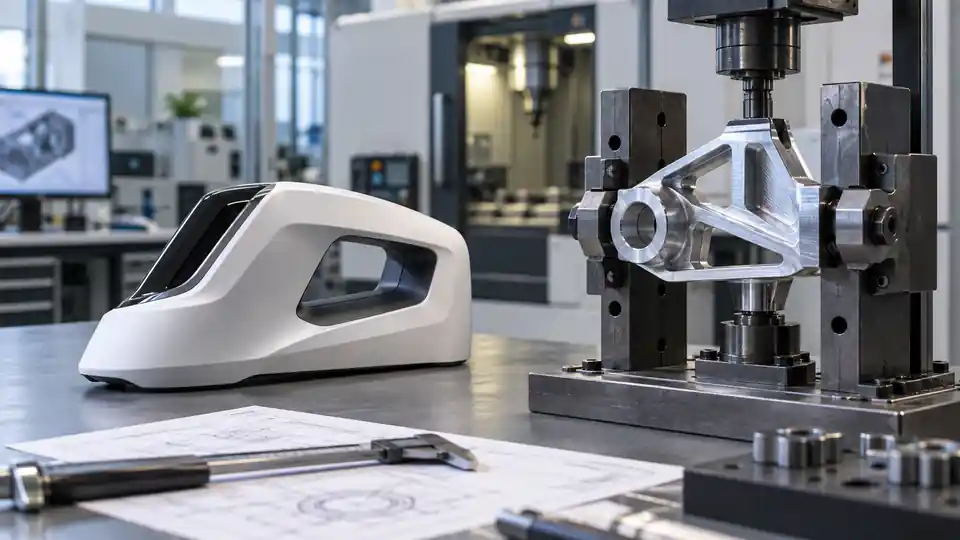
A visual prototype communicates size, form, color, texture, gaps, and perceived quality. A functional prototype is built to withstand defined loads, movement, temperature, fluid, wear, assembly, or other performance tests. One physical part can serve both purposes, but only when its material, geometry, finish, and acceptance plan support both decisions.
This visual vs functional CNC prototype guide helps engineering, design, and purchasing teams specify the right build. It shows which details must be authentic, which may be simulated, how CNC machining affects appearance and behavior, and how to prevent a beautiful model from being mistaken for verified hardware—or an engineering test piece from being judged as a final cosmetic sample.
Write Two Separate Decision Statements
Before choosing a process, write the visual decision and the functional decision independently.
A visual decision might be: “Approve the external housing proportions, control layout, parting lines, logo position, and black satin appearance for the next design review.”
A functional decision might be: “Verify that the bearing housing maintains shaft alignment under the specified radial load and temperature range for the planned test duration.”
These statements reveal different requirements. The visual prototype needs representative outer surfaces and viewing conditions. The functional prototype needs material, interfaces, datums, assembly state, and a test method. If both decisions are needed, define how one unit can support them without one test damaging the other.
What a Visual Prototype Should Prove
Visual prototypes support decisions about:
- overall form and scale;
- proportions and feature placement;
- line breaks, gaps, flushness, and transitions;
- color, gloss, texture, and reflectivity;
- branding, labels, and controls;
- perceived craftsmanship;
- stakeholder communication and photography; and
- appearance under intended lighting and viewing distance.
They do not automatically prove structural strength, thermal performance, sealing, fatigue life, or production capability. A model may use filler, paint, bonded inserts, hand finishing, or hidden supports that would be unacceptable in a functional test.
The build record should state “visual evaluation only” when that limitation matters.
What a Functional Prototype Should Prove
Functional prototypes support measurable engineering questions such as:
- assembly fit and interface alignment;
- static strength and stiffness;
- movement, friction, and wear;
- thermal conduction and expansion;
- pressure, flow, or leak performance;
- electrical grounding or shielding interfaces;
- bearing, seal, and fastener behavior;
- vibration or impact response;
- serviceability and tool access; and
- performance under environmental exposure.
Function depends on product state. Define loads, restraints, torque, temperature, lubricant, pressure, duty cycle, mating components, and failure criteria. “It worked” without test conditions is not transferable evidence.
Comparison Table
| Planning factor | Visual prototype | Functional prototype |
|---|---|---|
| Primary output | Appearance approval | Engineering performance evidence |
| Geometry emphasis | Visible form, gaps, transitions | Load paths, interfaces, datums, internal features |
| Material fidelity | May use substitute if appearance is reproduced | Must preserve properties relevant to the test |
| Tolerances | Cosmetic and assembly-display needs | Derived from function and measurement uncertainty |
| Finish | Color, gloss, texture, workmanship | Friction, sealing, wear, corrosion, thermal/electrical effects |
| Quantity | Review views, variants, or stakeholder sets | Test matrix, destructive tests, controls, repeats |
| Inspection | Master comparison and visual criteria | Actual dimensions and technical test results |
| Rework | Hand finishing may be acceptable if disclosed | Rework must not change the behavior being evaluated |
| Configuration | Appearance variant identity | Full unit, material, process, assembly, and test identity |
| Typical risk | Subjective approval under uncontrolled viewing | Invalid result from nonrepresentative material or setup |
When CNC Machining Fits a Visual Build
CNC machining is useful when a visual model needs crisp edges, metal mass, realistic gaps, engraved details, machined textures, threaded assembly, or durable handling. It can make external geometry directly from CAD and support several appearance variants without hard tooling.
However, an as-machined aluminum part does not look like anodized production hardware, and a painted machined block does not reproduce molded texture or parting lines unless these are deliberately simulated. If the future process is molding, casting, stamping, or extrusion, note the appearance differences.
Visual fidelity may justify nonfunctional choices: split a hard-to-machine body into bonded pieces, enlarge a hidden clearance, use a cosmetic insert, or fill tool marks. Record these modifications so no one uses the model for fit or strength approval.
Decide What Can Stay Digital
High-quality rendering, virtual reality, and digital mockups can resolve some appearance questions before material is cut. They are useful for comparing proportions, color concepts, label placement, and environments. They also allow fast stakeholder feedback across many variants.
A physical model remains valuable when the decision depends on scale perception, touch, real lighting, edge highlights, gaps, surface texture, mass, grip, or the relationship among assembled parts. Screens cannot reproduce every material interaction, and display calibration varies.
Use digital review to narrow alternatives, then build physical samples for the attributes that require them. Record rendering assumptions such as material model, lighting, camera, and color-management workflow. A rendered finish is not a production approval unless the product procedure explicitly treats it that way.
For functional questions, simulation can also reduce the hardware matrix. Finite-element, thermal, or flow analysis helps select cases and instrument locations, but the model’s boundary conditions and material data need verification. Prototype testing should confirm the risks and assumptions that remain uncertain.
Use Hybrid Prototypes Deliberately
A hybrid assembly may combine CNC parts with additive components, sheet metal, stock extrusion, commercial fasteners, temporary wiring, and hand-built fixtures. This can be the best way to learn quickly. The danger is allowing each substitute to become invisible.
Create a deviation map showing which components and features are production-intent, representative only, or simulated. Note how each difference affects appearance, fit, load path, thermal behavior, sealing, wear, and test interpretation. Review the map before the build and again before approving results.
For example, a CNC-machined housing may represent stiffness and interfaces while an additively made cover represents only external shape. If the cover contributes structural support in the final design, that assembly cannot validate the complete load path. If temporary black paint represents future anodize, it may support color direction but not wear, conductivity, or corrosion evidence.
Mark hybrid units clearly and retain their bill of materials. Never let them enter a pilot or customer trial under a production-equivalent label without authorized review.
When CNC Machining Fits a Functional Build
CNC machining is a strong choice when performance depends on metal or engineering-plastic properties, precise interfaces, flatness, bores, sealing lands, threaded connections, or internal flow geometry. It produces controlled features without waiting for production tooling.
The route still affects evidence. Machined wrought material can differ from cast, forged, molded, or additively manufactured production material in grain flow, porosity, residual stress, anisotropy, wall transitions, and surface condition. CNC may prove geometric architecture and interface behavior while leaving process-dependent tests for later.
Identify whether the prototype is production-intent, material-representative, geometry-representative, or only functionally analogous. Avoid the single word “representative” without saying what it represents.
Use a Fidelity Matrix
Rate fidelity by attribute instead of classifying the whole part as “high fidelity.”
| Attribute | Required fidelity | Reason | Accepted deviation | Evidence limitation |
|---|---|---|---|---|
| External silhouette | High | Visual approval | None beyond master | Supports form review |
| Black finish | High visually | Color/gloss decision | Substitute coating allowed | Does not prove production corrosion |
| Material modulus | High | Deflection test | Production alloy required | Supports stiffness result |
| Internal cosmetic surface | Low | Not visible or functional | As-machined | No appearance conclusion |
| Bearing seat | High | Fit and alignment | Drawing tolerance | Supports assembly test |
| Fastener type | Medium | Access review | Same envelope/drive | Torque result not transferable |
Complete the matrix before the RFQ. It helps the supplier recommend a lower-cost route without weakening the intended decision.
Specify Visual Acceptance Objectively
“Premium finish” and “looks good” invite disagreement. Define the viewing condition and comparison method.
Include:
- approved master sample or color/texture reference;
- illuminated environment or light source;
- viewing distance and angle;
- surface zones and cosmetic classes;
- allowed and prohibited defects;
- boundary samples for marginal conditions;
- color and gloss measurement where needed;
- grain or brush direction;
- coating thickness and masking when dimensional; and
- approver and disposition path.
Human visual assessment remains important, but lighting, observer, orientation, and surrounding colors influence perception. NIST’s Surface and Interface Metrology Group identifies surface color, appearance, reflectance, roughness, waviness, and form as distinct measurement areas. A single Ra value cannot define all visible quality.
Use photographs carefully
Photos help document location and severity, but cameras, white balance, exposure, compression, and displays change appearance. Include scale, consistent lighting, orientation, and an identified reference. Do not approve color from an uncontrolled phone image when the final decision requires a physical master or instrument.
Specify Functional Acceptance Quantitatively
A functional test needs a controlled protocol. State:
- requirement and acceptance limit;
- unit and configuration;
- preload, torque, restraint, and assembly sequence;
- load or stimulus profile;
- temperature, humidity, fluid, and other environment;
- duration and number of cycles;
- instrumentation, range, resolution, and calibration;
- sampling and repeat requirements;
- data acquisition and analysis;
- failure definition; and
- approved deviations.
Separate input conditions from results. If a bracket deflects 0.4 mm, that value means little without load point, force, restraint, temperature, and measurement location.
Select Materials by the Attribute Under Review
A visual model may need only similar color response and surface quality. A functional model may need elastic modulus, yield behavior, density, thermal conductivity, coefficient of expansion, corrosion, wear, creep, chemical resistance, or outgassing.
For visual anodized aluminum, alloy and surface history affect color and shade. A cosmetic result on one alloy or heat may not define another. For a functional plastic bearing, a material with similar tensile strength may have different creep and moisture response.
Create an approved substitution statement naming the changed properties and tests that become invalid. If both appearance and function matter, production-intent material may be the simplest path despite higher cost.
Control Geometry by Purpose
Visual prototypes need smooth transitions, consistent gaps, sharp graphic boundaries, and silhouette accuracy. Functional prototypes need datum relationships, fit, load-path geometry, sealing surfaces, wall thickness, and accessible inspection.
Mark each feature as:
- visual-critical;
- function-critical;
- both; or
- noncritical for this build.
A feature in the “both” class needs the stronger combined requirement. A visible bearing cover, for example, may need cosmetic concentricity and a functional bearing fit. Coordinate finishing allowances so appearance processing does not destroy fit.
Plan Surface Finish and Coating
Appearance processes can change dimensions and function. Anodizing, plating, paint, powder coating, blasting, polishing, and brushing affect thickness, growth, edge buildup, friction, electrical contact, sealing, wear, and color.
For a visual-only part, a substitute coating may be acceptable. Label it. For a functional unit, define whether the final process is needed and which surfaces are masked or post-machined. Inspect critical dimensions in the state required by the drawing.
Do not use a visually smooth hand-polished surface to infer the performance of a production-ground or molded surface. Texture parameters, lay, waviness, defects, and surface chemistry can matter independently.
Define Cosmetic Zones
Divide the part or assembly into zones based on normal visibility and importance. Zone A may be continuously visible to the user; Zone B visible during handling; Zone C hidden after assembly. Define criteria for each.
Provide marked images or drawings showing boundaries and edge treatment. State whether fixture marks, rack marks, color variation, machining witness, scratches, dents, and tool blend are permitted. Specify which direction a brushed or machined pattern should run.
Avoid imposing Zone A requirements on hidden internal faces. It adds manual work and can blur attention from the truly visible surfaces.
Design the Functional Test Around the Interface
Many CNC prototypes fail because test fixtures do not reproduce mating conditions. Use representative fasteners, torque, bearings, seals, adhesives, fluids, connectors, and support surfaces. Define datum and assembly sequence.
Check whether the fixture is too stiff or too compliant, adds cooling, misaligns the part, or bypasses a load path. Instrument mounting should not reinforce the hardware. For thermal tests, account for interface materials and contact pressure. For leak tests, define port configuration and seal reuse.
Record fixture and test-software revision with the unit. A result is a property of the complete test configuration, not of the machined part alone.
Plan Quantity and Sequence
Visual reviews may need several color, texture, or geometry variants. One master and boundary samples can be more useful than many identical parts. Account for samples consumed by finishing trials.
Functional quantity follows tests. Separate destructive specimens, fatigue units, environmental exposures, controls, assembly trials, and retained units. Avoid running appearance approval after destructive or contaminating testing.
When one unit serves both purposes, sequence activities deliberately:
- receive and inspect;
- photograph initial condition;
- conduct visual review under controlled conditions;
- record approval or defects;
- perform nondestructive functional checks;
- conduct destructive or contaminating tests last; and
- record final disposition.
Control Rework and Hand Finishing
Visual prototypes often receive sanding, filling, polishing, paint touch-up, or hand fitting. These operations can be legitimate when disclosed. Record who performed them, where, and what geometry or material they changed.
Functional prototypes need stricter assessment. Blending a fillet can change stress concentration; lapping a bore changes fit; heating a part for rework can change material or coating; sealant can hide a leak path. Approve rework before test and mark the affected unit.
Do not average results from reworked and untouched units without evaluating the difference.
Inspect and Document the Two Builds Differently
For visual parts, retain the approved master, viewing setup, photos, defect map, color/gloss results if used, and approver. Dimensional inspection should cover form, gaps, alignment, and features that influence appearance.
For functional parts, retain the controlled drawing, actual measurements for critical characteristics, material/process evidence, assembly record, test protocol, raw data, anomalies, and configuration. Link every result to a serial or unit ID.
A supplier’s standard inspection report may not include visual criteria or test configuration. Define the deliverable instead of assuming one quality package serves both.
Avoid False Evidence
A cosmetic sample is presented as production finish
Hand polishing and custom paint may not be scalable. Label the process and repeat approval on production-intent finishing.
A functional test uses nonrepresentative material
Performance is attributed to the design although stiffness, thermal, wear, or environmental properties differ. Limit the conclusion or rebuild.
Appearance is approved under office lighting only
The product later looks different in its actual environment. Define light, angle, and distance.
A prototype passes because the fixture helps it
The test fixture supplies support or alignment absent in use. Review the load path and boundary conditions.
Hand-fit assembly masks tolerance problems
Parts are selectively matched or modified. Record actual dimensions and assemble without unapproved adjustments.
One unit carries every test
Earlier testing damages or conditions it. Allocate units and sequence tests based on interactions.
Cost and Schedule Tradeoffs
Visual cost increases with cosmetic zones, manual finishing, color matching, multiple variants, display quality, and fast review cycles. Functional cost increases with representative material, tight interfaces, test fixtures, instrumentation, inspection, traceability, and destructive quantity.
Combining both goals may save one set of machining but add risk. A cosmetic finish can delay functional testing; a load test can scratch the sample; a hand correction can invalidate measurement. Compare the cost of one dual-purpose unit with two focused builds and the consequence of repeated testing.
Ask suppliers to separate:
- engineering and DFM;
- material and quantity;
- programming and workholding;
- machining;
- cosmetic preparation and finish;
- functional inspection;
- test fixtures and testing;
- variant or iteration allowance; and
- expedited schedule risk.
Supplier Brief for a Visual Prototype
Provide:
- master CAD and marked visible surfaces;
- target form, gaps, and transitions;
- color, gloss, texture, and grain references;
- cosmetic zones and defect limits;
- viewing and photography conditions;
- permitted filler, bond, or simulated features;
- required moving/assembly features;
- variant quantity and labels; and
- approval and sample-retention plan.
State explicitly which properties are not being approved.
Supplier Brief for a Functional Prototype
Provide:
- controlled model/drawing and unit identity;
- functional requirements and acceptance limits;
- material and process fidelity;
- critical dimensions, datums, fits, and surfaces;
- mating components and assembly instructions;
- test protocol and fixture interfaces;
- environmental and duty conditions;
- inspection and record package;
- approved substitutions/deviations; and
- change and rework authorization.
State which later production-process effects remain unverified.
Decision Checklist
- What exact approval will the prototype support?
- Is appearance, function, or both under review?
- Which attributes must match production?
- Which substitutions are allowed and what evidence do they invalidate?
- Are visual criteria objective enough for two reviewers to agree?
- Are functional conditions and limits measurable?
- Does CNC machining reproduce the relevant material/process behavior?
- Are finish thickness and masking included in dimensional planning?
- Is quantity sufficient for variants, repeats, and destructive tests?
- Are units and configurations uniquely identified?
- Are rework and hand finishing recorded?
- Will one test affect another?
- Who approves each result and what happens after failure?
Preserve the Approval Record
Visual and functional reviews often end in a meeting where preferences and technical conclusions become mixed. Use separate approval fields. Record the unit, configuration, viewing/test condition, accepted attributes, rejected attributes, limitations, actions, approver, and date.
For a conditional visual approval, state the exact change and whether another physical sample is required. For a functional failure, retain raw data and the failed unit until investigation is complete. Do not overwrite photographs or reports after rework; issue a new revision linked to the original.
When one build supports both decisions, the record should show two outcomes. An approved appearance does not cancel a failed load test, and a passing function test does not authorize the color or workmanship. This distinction prevents a later team from citing a general “prototype approved” status outside its scope.
Build the Prototype Around the Decision
A visual prototype succeeds when stakeholders can approve defined appearance attributes under controlled viewing. A functional prototype succeeds when a known configuration produces valid evidence against a technical requirement. CNC machining can deliver either, but the chosen material, tolerances, finish, inspection, and documentation must follow the intended decision.
Before closing the build, reconcile every unit and sample. Identify which are approved masters, which were tested or damaged, which contain unapproved rework, and which must be destroyed or retained. Clear disposition prevents a display model from later entering engineering testing or a failed test unit from being shown as an approved appearance sample.
For a QuickCNCs prototype RFQ, send the controlled CAD and drawing, mark visual and functional critical features, identify production process/material, describe the review or test, and list permitted substitutions. We can propose a machining and inspection scope that produces useful evidence without adding requirements that do not support the next decision.
Use rapid prototyping for the first decision-focused build, consult surface finishing where appearance controls the review, and submit separate visual and functional acceptance criteria through Request a Quote.