
Struggling to reduce manufacturing costs without sacrificing precision? You know that high-volume production demands efficiency, but choosing the right grinding method can feel like a gamble. The wrong decision can inflate your budget and delay your entire project, leaving you with costly rework.
A full economic analysis of centerless grinding involves calculating direct costs (labor, machine time, consumables), indirect costs (setup, maintenance), and then weighing them against its return on investment (ROI). This ROI comes from extremely high throughput, reduced labor per part, and superior surface finishes, making it exceptionally cost-effective for high-volume production runs of cylindrical parts.
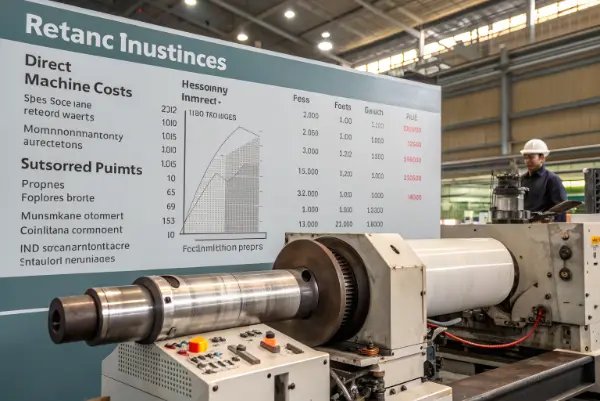
The numbers often look good on paper. Centerless grinding is famous for its speed and efficiency. But is it always the right answer? The true cost goes beyond just the cycle time. A real analysis means you have to look at everything—the setup, the tooling, the limitations, and how it stacks up against other methods. Let’s dive deep into the real cost factors and ROI considerations to see if it truly fits your project’s needs.
How Do You Accurately Calculate Grinding Costs?
You’re trying to budget for a project, but the cost estimates for grinding seem like a moving target. A wrong estimate can blow your budget or, worse, lead you to choose a less effective process, compromising part quality and causing major headaches down the line.
To calculate grinding cost, you must sum the machine time cost (hourly rate × cycle time), labor cost, abrasive wheel consumption cost, and setup costs. For high-volume jobs, you should amortize the setup cost across the entire production run. Don’t forget to factor in material and general factory overheads for a complete and accurate picture.
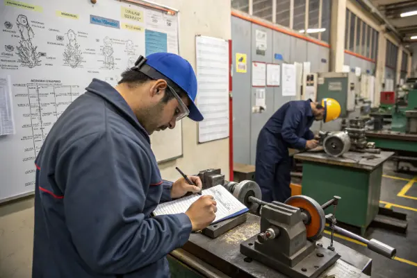
Breaking down the cost of any grinding operation, whether it’s centerless, cylindrical, or surface grinding, requires a structured approach. I always advise my clients, especially those like Alex who manage tight budgets for precision robotics, to think beyond the price per hour. The real cost is a combination of several key factors. We need to dissect each one to build a clear financial picture. It’s the only way to make a truly informed sourcing decision. I once helped a client who was hesitant about the setup cost for a 100,000-part run. By breaking it down, we saw the per-part cost was cents on the dollar compared to the alternative, saving them nearly 40% on their project.
Breaking Down the Core Cost Components
Let’s organize these costs into a simple framework. Understanding each component helps you see where your money is going and identify areas for potential savings.
| Cost Component | Description | Impact on Total Cost |
|---|---|---|
| Machine Time | The cost per hour to run the grinding machine, multiplied by the cycle time per part. | High Impact: This is often the largest cost driver, especially for complex parts requiring longer cycle times. |
| Labor Cost | The wage of the machine operator. In centerless grinding, one operator can often manage multiple machines. | Variable Impact: Highly automated processes reduce this cost per part, making it more efficient for large volumes. |
| Consumables | The cost of the grinding wheel and dressing tools, calculated on a per-part basis. | Medium Impact: High-quality wheels cost more upfront but may last longer and produce better parts, reducing overall cost. |
| Setup Cost | The one-time cost for labor and machine downtime required to configure the grinder for a specific job. | High Impact (for small runs): This cost is significant for prototypes but becomes negligible when spread across thousands of parts. |
| Overhead | Indirect costs like factory electricity, maintenance, quality inspection, and administrative support. | Low to Medium Impact: Usually applied as a percentage of the direct costs. |
Practical Application: Centerless vs. Cylindrical Grinding
Imagine you need 50,000 small cylindrical pins.
- Cylindrical Grinding: Each part must be manually or robotically loaded between centers. The cycle time is longer. Labor is more intensive.
- Centerless Grinding: After the initial setup, parts are fed through continuously. The cycle time is a fraction of cylindrical grinding.
While the initial setup for centerless grinding might take several hours and seem expensive, the cost is amortized. If the setup is $500, for a 50,000-part run, that adds only $0.01 to each part. The dramatic reduction in cycle time and labor far outweighs this initial investment, showcasing its incredible ROI for high-volume scenarios.
How Can You Guarantee Concentricity with Internal Centerless Grinding?
You’re designing a critical hollow component, like a bearing race or a hydraulic sleeve. You need the inner diameter (ID) and outer diameter (OD) to be perfectly concentric. Any eccentricity could cause vibration, uneven wear, and catastrophic failure in the final assembly, a risk you simply can’t take.
To maintain excellent concentricity between the inner and outer diameters, the shoe-type internal centerless grinding method is the most reliable solution. In this process, the workpiece is supported externally by two shoes and a regulating wheel while the grinding wheel works on the internal diameter. This external reference ensures the ID is ground perfectly concentric to the pre-finished OD.
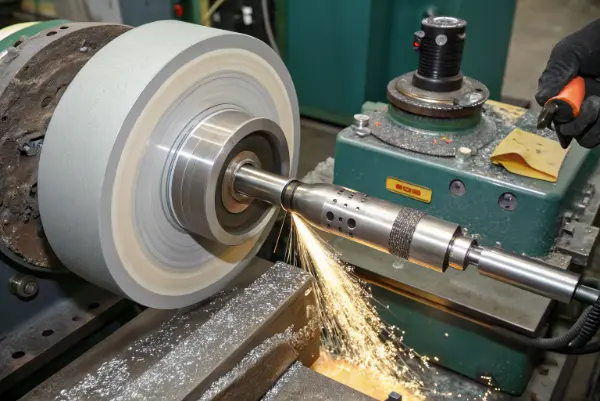
When an engineer like Alex from Germany comes to me with a design for a robotic joint, concentricity is non-negotiable. For a part to rotate smoothly at high speeds under load, the alignment between the ID and OD must be almost perfect. Traditional methods, where you grip the part in a chuck to grind the ID, can introduce small errors. The clamping force itself can distort the part slightly, and any imperfection in the chuck’s grip will be transferred to the final part. This is where the elegance of shoe-type internal centerless grinding really shines. It completely bypasses the problems associated with clamping.
How Shoe-Type Grinding Achieves Superior Concentricity
The magic of this method lies in its unique support system. Instead of being held by a chuck, the workpiece rests on a foundation that uses its own outer surface as the reference point.
- The Setup: The workpiece, which already has its outer diameter ground to a precise finish, is placed between three points.
- Support Shoe: A fixed, stationary shoe that provides a solid base.
- Pressure Shoe: A second shoe that applies gentle, consistent pressure to hold the workpiece in place against the support shoe and regulating wheel.
- Regulating Wheel: This wheel rotates the workpiece at a controlled speed. Its job is purely to drive the part; it doesn’t provide the primary locating accuracy.
- The Grinding Action: While the workpiece is securely nested and rotating, the internal grinding wheel enters the bore and begins to remove material.
- The Result: Because the workpiece’s location is dictated entirely by its own external surface, the ground internal diameter is inherently concentric to that external surface. Any existing "high spots" on the OD don’t affect the ID’s roundness or its position relative to the OD’s central axis.
When is This Method Essential?
This technique is the go-to solution for high-performance components where concentricity is a critical functional requirement.
- Bearing Races: For smooth, quiet, and long-lasting bearing performance, the inner and outer raceways must be perfectly aligned.
- Hydraulic and Pneumatic Sleeves: In hydraulic spools and valves, concentricity ensures a proper seal and prevents leakage, enabling precise control of fluid or air.
- Gears and Bushings for Robotics: In Alex’s field, concentric bushings in robotic arms prevent "slop" or backlash, ensuring the robot’s movements are precise and repeatable.
By using the OD as the datum, shoe-type internal centerless grinding removes the concentricity errors that can be introduced by chucking. It’s a clever manufacturing solution that directly addresses a critical engineering challenge.
What Are the Key Parameters of a Grinding Wheel You Must Know?
Your parts are coming off the grinder with burn marks, a poor surface finish, or incorrect dimensions. This leads to scrapped parts, project delays, and a lot of frustration. Often, the root cause is a mismatch between the grinding wheel and the job. The problem is, a grinding wheel’s specification code looks like gibberish.
The five principal parameters of a grinding wheel are the abrasive type, grain size, bond type, grade (hardness), and structure. These are communicated through a standard code on the wheel. Understanding them is crucial for matching the wheel to the workpiece material, desired finish, and production speed, directly impacting the quality and efficiency of your grinding operation.
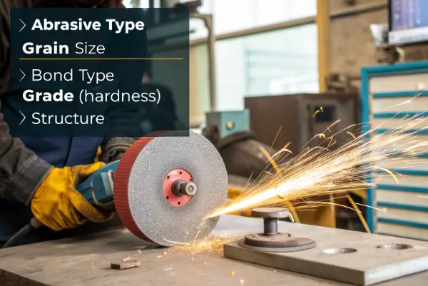
I remember working on a project with a new engineer who was struggling with grinding hardened tool steel. The parts were overheating and cracking. He was using a standard aluminum oxide wheel that was simply too soft and loading up instantly. We switched to a cubic boron nitride (CBN) wheel with a vitrified bond, and the problem vanished. The parts came out perfect. This experience taught me that knowing these five parameters isn’t just academic; it’s the key to solving real-world manufacturing problems and avoiding costly mistakes. It’s the difference between success and failure on the shop floor.
Decoding the Grinding Wheel Specification
That long string of letters and numbers on a wheel is a recipe for its performance. Let’s break it down into the five core elements.
| Parameter | Description | Typical Options & Impact |
|---|---|---|
| 1. Abrasive Type | The cutting material that does the work. | A (Aluminum Oxide): For steels. C (Silicon Carbide): For cast iron, non-ferrous metals. CBN/D (Cubic Boron Nitride/Diamond): Superabrasives for hardened steels and ceramics. |
| 2. Grain Size | The physical size of the abrasive grains, from coarse to very fine. | Coarse (e.g., 24, 36): High material removal, rough finish. Fine (e.g., 100, 120): Low material removal, excellent surface finish. |
| 3. Grade (Hardness) | The strength of the bond holding the grains. It determines how easily old, dull grains break away to expose new, sharp ones. | Soft (e.g., G, H, I): For hard materials or large contact areas. Grains break away easily. Hard (e.g., P, Q, R): For soft materials or maintaining intricate profiles. Grains are held tightly. |
| 4. Structure | The spacing between the abrasive grains. It defines the chip clearance in the wheel. | Dense (e.g., 1, 2, 3): Less space. Good for fine finishing and holding form. Open (e.g., 10, 11, 12): More space for chip clearance. Good for high material removal rates; prevents wheel "loading." |
| 5. Bond Type | The "glue" that holds the grains together. This affects the wheel’s strength, flexibility, and operating speed. | V (Vitrified): Most common. Strong, rigid, porous. For precision work. R (Rubber): Flexible. Provides a very fine finish. B (Resinoid): Strong and shock-resistant. Used for high-speed rough grinding and cutoff wheels. |
Putting It All Together for a Precision Job
Let’s say you’re grinding a hardened steel shaft for a robotic arm, a typical job for an engineer like Alex. You need a fine finish and tight tolerance.
- Abrasive: It’s a hard steel, so a standard Aluminum Oxide (
A) or a superabrasive like CBN would be ideal. - Grain Size: You need a fine finish, so you’d choose a higher number, like
80or100. - Grade: The material is hard, so you need a softer grade wheel (
IorJ) that will break down and self-sharpen rather than burn the part. - Structure: A medium structure (
5or6) provides a good balance between finish and cutting ability. - Bond: For precision and rigidity, a Vitrified (
V) bond is the perfect choice.
A wheel with a code like A 80 J 5 V would be a great starting point for this application. Understanding this code empowers you to communicate clearly with suppliers and troubleshoot quality issues effectively.
What Are the Real Limitations of Centerless Grinding?
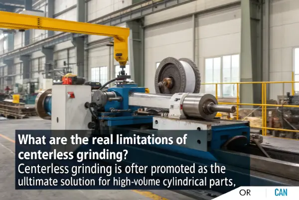
Centerless grinding is often promoted as the ultimate solution for high-volume cylindrical parts, promising speed and precision. But this can be misleading. Believing it’s a one-size-fits-all process can lead you to specify it for jobs where it’s inefficient, or even impossible, creating costly design and production roadblocks.
The main limitations of centerless grinding are its unsuitability for low-volume runs due to long setup times, its inability to grind non-cylindrical features like keyways or flats simultaneously, and difficulty in ensuring perfect concentricity for parts with multiple diameters unless they are ground one diameter at a time. It is also not ideal for parts with heavy interruptions.
While centerless grinding is a powerhouse, it’s not a magic wand. I’ve seen engineers get stuck trying to apply it to the wrong kind of part. One client wanted to centerless grind a shaft that had a keyway along its entire length. The process just doesn’t work that way. The part needs a consistent, uninterrupted cylindrical surface to be properly supported and rotated by the regulating wheel. We had to switch to cylindrical grinding, which was slower but was the right process for the job. Understanding the boundaries of a process is just as important as knowing its strengths. It prevents you from wasting time and money going down the wrong path.
When Centerless Grinding Is NOT the Answer
Recognizing the limitations is key to making smart manufacturing choices. Here are the specific scenarios where you should consider alternatives.
1. Low Volume and Prototype Work
The biggest hurdle for centerless grinding is the setup time. Calibrating the angle of the regulating wheel, setting up the work rest blade, and dialing in the dimensions can take several hours.
- High Setup Cost: For a run of 10,000 parts, a 4-hour setup is easily absorbed. For 10 prototypes, that same setup cost makes each part prohibitively expensive.
- Alternative: For prototypes and small batches, traditional cylindrical grinding is far more economical because setup is much faster.
2. Parts with Non-Cylindrical Features
Centerless grinding relies on a simple, consistent cylindrical profile.
- Interruptions: Features like keyways, flats, or cross-holes will disrupt the smooth rotation and support, leading to inaccuracies and potential damage.
- Multi-Diameter Complexity: While thru-feed grinding is great for single-diameter parts, complex profiles with multiple diameters and shoulders require in-feed centerless grinding. This is slower and more complex, and sometimes parts with very different diameters are better suited for a CNC lathe or cylindrical grinder. For example, a shaft that is 20mm on one end and 80mm on the other is a poor candidate.
3. Parts Requiring Perfect Squareness
In centerless grinding, there is no direct control over the squareness of a face to the diameter.
- Face Grinding: The process only grinds the outer diameter. If you need a shoulder face to be perfectly perpendicular to the main body, you’ll need a secondary operation on a different machine.
- Alternative: A CNC lathe or a cylindrical grinder can turn the diameter and face the shoulder in the same setup, guaranteeing excellent squareness.
Understanding these limitations helps you use centerless grinding for what it does best: churning out massive quantities of simple, high-precision cylindrical parts at an unbeatable speed. For everything else, there are better tools for the job.
Conclusion
A thorough economic analysis reveals centerless grinding’s ROI shines in high-volume production, but its setup costs, and geometric limitations make it unsuitable for all jobs. Choose wisely.