
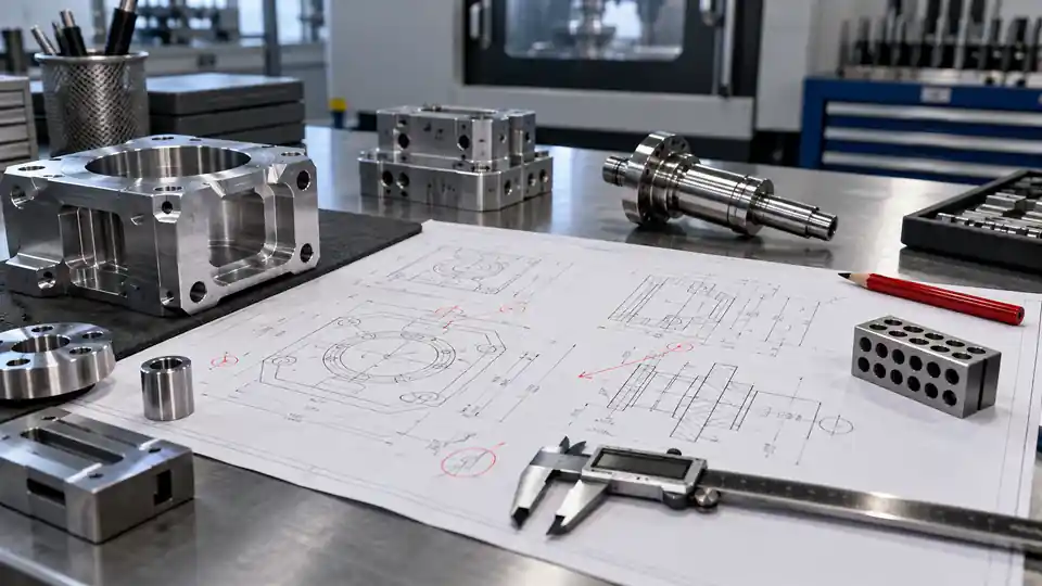
A 3D model can show a machine shop what the part looks like, but it rarely tells the whole manufacturing and inspection story. A quote-ready 2D production drawing establishes the controlled requirements that are difficult, ambiguous, or inappropriate to infer from CAD alone: tolerances, datums, threads, surface texture, material condition, finishing, inspection, and revision authority. The point of a drawing preflight is not to fill every empty space with a dimension. It is to give every bidder the same technical baseline so that price, lead time, and risk can be compared fairly.
This checklist is written for engineers and buyers preparing a CNC RFQ. It explains what belongs on the drawing, what may remain model-defined, how the model and drawing should work together, and which omissions are likely to produce clarification loops or inconsistent quotations. It is not a replacement for your organization’s drafting standard or a contract-specific requirement. The released drawing, purchase order, and applicable specifications remain the controlling documents.
What a CNC Production Drawing Must Accomplish
A useful production drawing has four jobs. First, it identifies the exact item and revision being quoted. Second, it defines the characteristics that make the part acceptable. Third, it tells the supplier which source controls if the model, drawing, specification, and purchase order conflict. Fourth, it defines the evidence required to release the shipment.
Those jobs are different from showing every geometric detail twice. If a controlled 3D model is the authority for nominal geometry, the drawing can use reduced dimensioning and clearly state that the model defines otherwise-undimensioned geometry. If the drawing is the sole dimensional authority, it must contain enough dimensions to manufacture and inspect the part without scaling a view or guessing from a screen image.
The shop should be able to answer these questions before estimating the job:
- Which part number and revision are being quoted?
- Which file defines nominal geometry?
- Which dimensions, tolerances, and notes define acceptance?
- What material and condition are required at shipment?
- Which surfaces receive finishing, coating, texture, or cosmetic control?
- What inspection records and certificates must accompany the parts?
- Who may approve a deviation or resolve a conflict?
If two qualified suppliers can reach different answers from the same RFQ package, the release is not ready.
Title Block and Document Identity
Start with the title block because it connects the drawing to the commercial order, CAD files, inspection report, and later repeat builds. At minimum, show the part number, unambiguous part name, drawing number if different, current revision, sheet number, units, scale, projection method, and approval information required by your document-control system.
The revision on the PDF must match the revision embedded in the filename, the 3D model package, the RFQ, and the purchase order. A date alone is not a reliable revision identifier. If several files belong to one release, include a short file manifest listing each filename, format, revision, and role. For example, state which file is the controlled solid model, which PDF is the controlled drawing, and whether any neutral model is supplied only for convenience.
Do not make a supplier decide which of two similarly named files is newer. Avoid filenames such as final.step, final2.step, or latest drawing.pdf. A stable convention such as part-number_revision_file-role.extension is easier to audit and less likely to leave an obsolete CAM program in use.
Units, scale, and projection
Units must be explicit even when they seem obvious from the dimensions. State millimeters or inches in the title block and repeat the unit in any exported inspection template. Confirm that the 3D model uses the same intended unit. A STEP file is often imported at the correct scale, but unit or exporter settings can still produce a part that is 25.4 times too large or too small.
Scale describes the printed view; it must not become a manufacturing method. Add a clear “do not scale drawing” instruction if it is part of your drafting practice. The supplier should use stated dimensions or model-defined geometry, never a measurement taken from a PDF view.
Identify first-angle or third-angle projection with the correct symbol. Mixed projection conventions can reverse the interpretation of side views, hole locations, or section direction, especially when a drawing moves between regions.
Define the Authority of the 3D Model and 2D Drawing
The RFQ should state how the two files interact. Three common release models are:
- Drawing-defined: the 2D drawing contains all dimensions needed for manufacture and inspection; the model is reference geometry.
- Model-defined with drawing requirements: the 3D model controls nominal geometry, while the drawing supplies tolerances, datums, notes, materials, and acceptance requirements.
- Model-based definition: the controlled model carries semantic or presented product manufacturing information, with an accompanying document that defines data authority and any non-geometric requirements.
Whichever approach you use, include a precedence statement. A practical model-defined note might say that the released 3D model controls nominal geometry except where a drawing dimension or note explicitly overrides it. Your quality system and applicable standard should determine the exact language.
Do not place a critical dimension on the drawing that disagrees with the model and expect the shop to “know what was meant.” Correct the source data or issue a controlled clarification before programming. Also avoid marking a screen capture or emailing an informal redline without updating the controlled baseline. That creates one revision for purchasing, another for CAM, and a third for inspection.
The principles in ASME Y14.5 are relevant when geometric dimensioning and tolerancing is used, but citing a standard does not repair an incomplete datum scheme or an unclear model/drawing precedence rule.
Dimension Only What Needs Control
More dimensions do not automatically make a better drawing. Redundant dimensions can create closed loops and contradictions. A production drawing should communicate design intent, functional interfaces, manufacturing limits, and inspection requirements without overconstraining noncritical geometry.
Check every dimension for four things:
- The dimension identifies the intended feature without relying on visual proximity.
- The tolerance is stated directly or is unambiguously covered by a general tolerance.
- The dimension is measured from a functional datum or appropriate origin.
- The dimension does not conflict with another dimension, the model, or a note.
Use reference dimensions only for information and mark them according to the applicable drafting convention. Do not let a reference value become the only definition of a critical feature. If basic dimensions are used with a geometric tolerance, make sure the feature control frame and datum references complete the requirement.
Holes, slots, pockets, and patterns
For holes, specify diameter, quantity, depth or through condition, location, and any counterbore, countersink, spotface, or bottom geometry. Distinguish a blind-hole drill depth from full-diameter usable depth. A conventional drill point leaves a conical bottom; if flat-bottom depth matters, show it.
For a hole pattern, identify the pattern clearly and define its location from the datum reference frame. Do not leave a supplier to combine an ordinate table, a copied note, and an unmarked centerline to reconstruct the pattern.
For slots and pockets, show width, length, depth, corner condition, and which dimensions may be model-defined. Identify open-ended versus closed features. Deep narrow pockets, small internal radii, and inaccessible undercuts deserve special attention because they can dominate tool choice and cycle time.
Threads and inserts
A thread callout should identify thread system, nominal size, pitch or threads per inch, class of fit, handedness if not right-hand, and required thread depth or through condition. Separate tap-drill depth from full-thread depth. If a thread insert is required, specify the insert standard or approved product, installed depth, tang treatment, locking feature if any, and whether installation occurs before or after coating.
Modeled helical geometry is usually unnecessary for quoting and can complicate file handling. A correctly defined cylindrical feature plus a controlled thread callout is typically clearer. If a thread is intentionally modeled for additive or another special process, state that explicitly.
Edge breaks, burrs, and sharp edges
“Break all sharp edges” is not enough when an edge seals, locates, cuts, or must remain sharp. State a default edge break range and identify exceptions. Define whether burrs are permitted at cross holes or internal intersections, how inaccessible burrs will be evaluated, and which edges must not be rounded.
For cosmetic parts, show the visible faces and allowed edge appearance. For sealing parts, define the transition between the seal surface and adjacent edge. A general deburr note should not silently change a functional corner radius.
Build a Functional Datum Scheme
Datums should reflect how the part locates and functions, not merely which faces are convenient to dimension. Review the primary, secondary, and tertiary datum features against assembly, clamping, and inspection. The primary datum establishes the first plane or axis; the secondary and tertiary datums remove the remaining degrees of freedom.
Common problems include datum symbols attached ambiguously to a size dimension, a datum feature too small or flexible to simulate reliably, and a datum order that does not match the mating interface. Another frequent error is placing profile or position controls without enough basic dimensions to locate the controlled feature.
Before release, walk through the inspection setup. Ask how the supplier will establish each datum, whether the feature is accessible, whether the part is measured free-state or restrained, and whether coating or heat treatment occurs before final measurement. If the intended setup cannot be described consistently, revise the datum scheme before requesting a quote.
Apply Tolerances Deliberately
General tolerances are useful for ordinary features, but they should not control everything by default. Confirm which dimensions fall under the title-block tolerance and which are governed by a specific tolerance, geometric control, or specification.
Avoid applying a tight decimal-place tolerance merely because a CAD dimension displays three digits. The number of displayed decimals should follow the drawing convention; it should not accidentally turn every noncritical dimension into a precision characteristic.
For each tight requirement, ask what function it protects and how it will be verified. Tolerances affect process selection, setup count, tool strategy, stabilization, inspection time, and scrap exposure. A supplier can quote more accurately when the drawing distinguishes true functional limits from conservative defaults.
Fits and mating features
For shafts, bores, bearings, pins, and press fits, identify the fit basis and final material condition. State whether dimensions apply before or after plating, anodizing, heat treatment, or assembly. If both mating components are controlled by your organization, review the combined tolerance stack rather than assigning the tightest possible limit to each part independently.
Do not use a nominal size and the word “press” as a fit specification. Define the permitted clearance or interference across the relevant temperature and material conditions. If selective assembly is allowed, state the grouping and traceability method.
Geometric tolerances
Check every feature control frame for the correct characteristic, tolerance zone, material condition modifier, and datum order. Position generally controls the location of features of size; profile can control complex surfaces; flatness applies without a datum; parallelism and perpendicularity require a datum; runout is evaluated by rotating a part about a datum axis.
Use geometric controls because they express function more accurately, not because they look more sophisticated. A misplaced modifier or an unstable datum can make a requirement harder—not clearer—to manufacture and inspect.
Material, Heat Treatment, and Material Evidence
Specify the material grade, governing specification where needed, and the condition or temper. “Aluminum” or “stainless steel” is not sufficient for a controlled RFQ. Aluminum 6061-T6, 7075-T651, stainless 17-4 PH H900, and annealed 304 have different properties, stock availability, stress behavior, and machining implications.
If an alternate grade is acceptable, define the approval route instead of leaving substitution open. State whether the supplier must provide a mill test report, heat or lot traceability, country-of-origin statement, or certificate of conformance. Evidence has a cost, so put it in the RFQ rather than asking for it after parts are complete.
For heat treatment, state the required final condition, applicable specification, hardness or mechanical-property requirement, and whether the treatment occurs before finish machining. Identify any distortion-sensitive characteristics that require post-treatment machining or verification.
Surface Texture, Coatings, and Cosmetic Requirements
Surface finish can mean machined roughness, a coating, a color, or a visual standard. Keep those requirements separate.
For machined texture, identify the parameter—such as Ra—its maximum or range, the surface to which it applies, and any lay or evaluation condition that matters. A blanket roughness requirement across the entire part can add unnecessary finishing and inspection. Mark only the functional zones that need it.
For anodize, plating, passivation, paint, or another coating, state the process type, class, color where applicable, masking requirements, rack-mark restrictions, and whether dimensions apply before or after coating. Coating buildup can change bores, threads, fits, and sealing faces. If a dimension is to be masked or finish-machined after coating, show that boundary clearly.
Cosmetic acceptance needs an actual viewing and comparison rule. Identify cosmetic faces, allowed defect types, distance, lighting, orientation, and an approved sample or visual standard when appearance is important. “No scratches” without a defined inspection condition is likely to produce different interpretations.
Notes and Referenced Specifications
Every note should be necessary, applicable, and controlled. Delete inherited notes that do not apply to the current part. A copied aerospace, medical, or cleanliness statement can create an obligation that no one intended and that bidders price differently.
When a note cites a standard or customer specification, include the document identifier and required revision or state how revision is controlled. Confirm that the supplier can obtain the document. Avoid contradictory requirements between the drawing, purchase order, and a referenced specification.
Review vague phrases such as “precision machining,” “best commercial practice,” “as required,” or “all dimensions critical.” Replace them with a measurable requirement or remove them. A note that cannot be inspected or objectively accepted should not be used as a substitute for engineering judgment.
Inspection and Quality Documentation
Define the inspection deliverable before quotation. The drawing establishes requirements; the RFQ or purchase order should establish the reporting scope. Options may include a certificate of conformance, material certificate, first-article report, dimensional inspection report, ballooned drawing, process certificate, or functional test result.
Identify which characteristics require recorded actual values. “Pass” may be sufficient for some attributes, but it does not support statistical analysis or a detailed first-article review. For a CMM report, require units, nominal values, limits, actual results, datum setup, and part/revision identity. If sampling is allowed, define the lot and sampling rule.
The QuickCNCs quality-assurance page describes available inspection capabilities, but the buyer still needs to specify the evidence appropriate to the part. Capability does not automatically establish the inspection scope for a particular order.
2D Drawing Preflight Table
| Review area | Confirm before RFQ | Typical consequence if missing |
|---|---|---|
| Document identity | Part number, name, revision, sheet, approval, and matching file manifest | Supplier quotes or machines the wrong release |
| Units and projection | Explicit units, model scale check, projection symbol, no drawing scaling | 25.4× scale error or misread view |
| Data authority | Clear model/drawing precedence and controlled source files | Conflicting geometry and inspection criteria |
| Dimensions | Complete functional definition without redundant conflicts | Clarifications, assumptions, or different quote baselines |
| Datums and GD&T | Functional datum sequence, complete basic dimensions, valid feature controls | Unrepeatable setup or disputed inspection |
| Holes and threads | Size, depth, fit/class, quantity, and secondary geometry | Wrong usable depth, assembly failure, added operations |
| Edges and burrs | Default edge break plus functional exceptions | Damaged seals, unsafe edges, internal burrs |
| Material | Grade, specification, condition/temper, permitted alternatives | Wrong stock, property risk, schedule change |
| Heat treatment | Final condition, sequence, hardness/properties, distortion plan | Rework, distortion, or noncompliant evidence |
| Surface requirements | Ra zones, coating type, masking, dimensional state, cosmetic faces | Unpriced finishing or fit changes |
| Inspection | Characteristics, actual-value reporting, sampling, records, tests | Unplanned inspection time or inadequate release data |
| Delivery | Quantity, packaging, ship-to, due date, and required documents | Incomparable quotes or shipment delay |
A Practical Release Sequence
1. Lock the product-data set
Export the controlled 3D model and drawing from the same approved revision. Open both exported files independently rather than trusting the authoring session. Check units, orientation, component count, suppressed features, and any drawing-to-model references. Create the file manifest.
2. Review functional interfaces
Mark mounting faces, bearing seats, sealing surfaces, locating pins, threaded joints, optical or electrical interfaces, and cosmetic zones. Confirm that each has a complete dimensional and acceptance definition. Review tolerance stacks across mating parts where relevant.
3. Conduct a manufacturing read-through
Read the package in the likely operation order: stock, rough machining, stabilization or heat treatment, finish machining, deburr, coating, cleaning, and inspection. Look for dimensions that change state between operations. Identify features that are difficult to access or inspect.
4. Conduct an inspection read-through
Imagine building a ballooned inspection plan. Can every controlled characteristic be uniquely identified? Are the datums usable? Are units and final condition explicit? Are visual requirements supported by a standard? Resolve open questions before the RFQ.
5. Compare files and commercial inputs
Verify that the quantity, revision, finish, inspection package, delivery location, packaging, and requested date match across the drawing, RFQ, and purchase order template. These inputs affect price and lead time even though they are not geometry.
6. Ask the supplier to list exceptions
Require each bidder to identify assumptions, exclusions, requested deviations, and alternative proposals. A quotation that silently changes a material, finish, tolerance, inspection scope, or delivery term is not comparable with one that follows the release.
What Not to Put on the Drawing
Do not use the drawing as a dumping ground for every purchasing term. Unit price, payment terms, shipping account, and general supplier instructions normally belong in the RFQ or purchase order. Keep the drawing focused on product definition and persistent manufacturing requirements.
Avoid proprietary process instructions unless the process itself is a design requirement. Specify the required result and evidence, then let the supplier propose the machining strategy. If wire EDM, grinding, or a named coating process is mandatory for functional reasons, say so and explain the controlled outcome.
Do not include confidential data that the supplier does not need. Apply the appropriate NDA and access controls separately. Mark export-controlled or customer-restricted data according to the governing policy.
Final CNC Drawing Checklist
Before sending the RFQ, confirm all of the following:
- The part number, drawing number, revision, and filenames agree.
- The 3D model and PDF open correctly outside the authoring CAD system.
- Units, scale, and first-angle or third-angle projection are explicit.
- The authority of the model and drawing is stated.
- Nominal geometry and controlled dimensions do not conflict.
- General tolerances are appropriate and specific tolerances override them clearly.
- The datum reference frame matches function and can be simulated for inspection.
- Every GD&T control has the required basic dimensions and valid datum references.
- Hole, slot, pocket, chamfer, counterbore, and countersink definitions are complete.
- Thread size, pitch, class, depth, and insert requirements are complete.
- Edge-break, deburr, and sharp-edge exceptions are identified.
- Material grade, specification, and condition or temper are stated.
- Heat treatment and dimensional sequence are defined.
- Surface texture applies only to the intended zones.
- Coating, color, masking, rack marks, and pre- or post-coating dimensions are defined.
- Cosmetic faces and visual acceptance conditions are identified.
- Referenced specifications are relevant, available, and revision-controlled.
- Required certificates, inspection reports, sampling, and tests are stated.
- Quantity, packaging, delivery, and ship-to data are included in the RFQ.
- The package contains no superseded files, informal redlines, or unexplained alternatives.
Sending the Package for Quotation
A complete drawing does not eliminate supplier questions; it makes the remaining questions useful. The supplier can focus on manufacturability, process options, cost drivers, lead-time risk, and proposed improvements instead of reconstructing basic requirements.
Send the native or neutral 3D model, controlled PDF drawing, file manifest, quantities, inspection/documentation scope, finishing requirements, and delivery information together. If a characteristic is unresolved, label it openly as a quotation assumption and identify when it will be frozen. Do not let each bidder invent a different answer.
QuickCNCs can review the package against its CNC machining services and identify missing information during quotation. When the model and drawing are ready, use the Request a Quote page and include the controlled files, target quantity, material, finish, inspection needs, and delivery destination. A disciplined preflight gives the engineering and purchasing teams a cleaner technical comparison—and gives the selected shop a stable baseline for programming, inspection, and repeat production.