
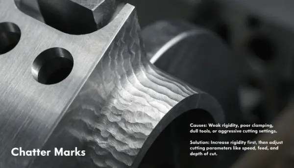
Have you ever looked at a freshly machined part and seen ugly wavy lines on the surface? Those are chatter marks. They ruin good parts, waste material, and cost you time. The good news? You can stop them.
Chatter marks are surface ripples caused by vibration between the cutting tool and the workpiece. They come from weak rigidity, poor clamping, dull tools, or aggressive cutting settings. The best fix is to boost rigidity first, then fine-tune speed, feed, and depth of cut.
I have spent years helping engineers like Alex solve this exact problem. Chatter looks simple, but it has many hidden causes. Let me walk you through what creates it and how to get rid of it for good.
What causes chatter in CNC?
You set up the job, start the cut, and hear a loud screaming noise. The surface comes out rough and wavy. Frustrating, right? The root cause is almost always vibration.
Chatter in CNC comes from vibration between the tool and the workpiece. The main triggers are weak machine rigidity, loose clamping, dull or long tools, wrong cutting parameters, and resonance. When the machine, tool, and part hit a natural vibration frequency, chatter shows up fast.
The five main sources
Let me break down where chatter really comes from. I see these problems again and again in real shops.
| Cause | What goes wrong |
|---|---|
| Machine rigidity | Worn guide rails, low spindle precision, weak setup |
| Workholding | Loose clamps, thin parts, poor fixture support |
| Tooling | Dull tools, long overhang, wrong geometry |
| Cutting parameters | Speed, feed, or depth too aggressive |
| Resonance | Machine, tool, and part match a vibration frequency |
Each one feeds the others. A dull tool pushes harder. Harder pushing shakes a weak fixture. A weak fixture lets the part move. That movement grows into a loud rattle and leaves marks.
I once had a client with a long end mill cutting a thin plate. The tool hung out too far. The clamps were loose. The spindle ran too fast. Three small mistakes stacked up into one big problem. Once we fixed all three, the chatter vanished. So you must look at the whole system, not just one part. Chatter is rarely caused by a single thing.
Why does chattering appear in a machined surface?
You expect a smooth, shiny finish. Instead you get a rippled, wavy texture. Why does this keep happening even when your machine looks fine?
Chatter appears on a surface because the tool bounces in and out as it cuts. This bouncing repeats at a steady rhythm and leaves a wave pattern. It often happens when the cut excites a natural frequency in the machine, tool, or part, making the vibration grow instead of fading.
How vibration becomes a visible mark
Think of pushing a child on a swing. If you push at the right moment each time, the swing goes higher and higher. Cutting works the same way. Each tooth of the cutter gives a small push. If those pushes line up with the natural vibration of the setup, the motion grows. This is called resonance.
When this happens, the tool digs deeper, then springs back, then digs again. This repeats many times per second. Each bounce leaves a tiny mark. Together those marks form the wavy lines you see.
Two common types
| Type | What causes it |
|---|---|
| Forced chatter | An outside source, like an unbalanced spindle or bad gear |
| Self-excited chatter | The cut itself feeds the vibration through resonance |
Self-excited chatter is the worst kind. It grows on its own. Even a tiny vibration can build into a loud rattle within seconds. That is why a part can start cutting fine and then suddenly turn rough. The system crossed into an unstable zone. Knowing this helps you react fast and stop the cycle early.
How to get rid of chatter marks in machining?
You see chatter starting. Do you panic and slam the feed down? Many people do. But slowing the machine is often the wrong first move. Let me show you a smarter order.
To get rid of chatter marks, follow this order: tighten the setup, shorten the tool stickout, swap in a sharper tool, then make small spindle-speed changes. Fix rigidity before you touch the numbers. This finds the root cause faster than just slowing the machine down.
A step-by-step troubleshooting plan
I always teach this simple ladder. Start at the top and work down.
- Tighten the setup. Check every clamp and bolt. Make sure the part cannot move.
- Shorten the tool overhang. Pull the tool back into the holder. A shorter tool is much stiffer.
- Swap in a sharper tool. A dull edge pushes harder and shakes more. Fresh edges cut clean.
- Make small RPM changes. Shift the spindle speed by a little. You may move out of the resonance zone.
- Rebalance feed and depth. Adjust these together until the cut sounds steady.
Why this order works
| Step | Why it helps |
|---|---|
| Tighten setup | Removes the biggest source of movement |
| Shorten tool | Raises rigidity right at the cut |
| Sharp tool | Lowers cutting force and noise |
| Small RPM shift | Escapes resonance without losing speed |
Here is a real example. A long end mill left wavy marks on a thin part. We reduced the overhang, improved the clamping, and nudged the spindle speed up a touch. The vibration disappeared. We did not slow the whole job. We just fixed the weak links. That kept the cycle time short and the finish smooth.
How to prevent chatter before it starts?
Fixing chatter mid-job is stressful. Stopping it before it begins is much better. So how do you set up a job that stays stable from the first cut?
To prevent chatter, build rigidity into your whole setup. Use short tools, stiff holders, and strong fixturing. Keep your machine maintained and level. Pick the right tool for the material. Then choose balanced speeds and feeds, and test critical cuts before full production.
Smart tooling and design choices
Some tools are made to fight vibration. Variable pitch and variable helix end mills change the spacing of their teeth. This breaks the steady rhythm that builds resonance. I recommend them for tough jobs.
You can also use dynamic damping systems and stability lobe diagrams. A stability lobe diagram shows you which spindle speeds stay stable. You pick a speed inside a safe zone instead of guessing.
A prevention checklist
| Area | Action |
|---|---|
| Rigidity | Short overhang, stiff holders, solid clamps |
| Tooling | Sharp edges, right geometry, variable pitch tools |
| Parameters | Balanced speed, feed, and depth of cut |
| Toolpath | Vary step-over and depth to break resonance |
| Maintenance | Check spindle, level the machine, tighten parts |
| Monitoring | Use vibration sensors on critical jobs |
One trick many people miss is the toolpath. If you vary the step-over and depth of cut as you program, you disrupt the resonance cycle. The vibration never gets a steady rhythm to grow on. Small structural supports near thin features also help a lot. At QuickCNCs, we plan all of this before we cut a single chip. That is how we hit tight tolerances like ±0.01mm and still deliver fast. Prevention always beats repair.
Conclusion
Chatter comes from vibration. Fix rigidity first, then sharpen tools, then tune speeds. Plan ahead, and your parts come out smooth every time.