
Material-condition modifiers let a drawing connect feature size with allowable geometric variation. Used correctly, they protect assembly or minimum wall thickness without forcing every part to hold the same geometric tolerance at every actual size. Used carelessly, they create disputes between a supplier’s CMM report, a functional gage, and the buyer’s interpretation.
This MMC bonus tolerance CNC guide explains maximum material condition (MMC), least material condition (LMC), regardless of feature size (RFS), virtual condition, bonus tolerance, datum mobility, and practical inspection. The governing drawing standard and edition remain controlling; ASME Y14.5 and the ISO GPS system use related concepts but should not be mixed symbol by symbol without an approved interpretation.
Start with a Feature of Size
MMC and LMC apply to features of size, not to any surface merely because it has a dimension. Typical examples are a cylindrical hole, a shaft diameter, a slot formed by two opposed parallel planes, or a tab width. The feature has an actual size within stated limits and a derived median line or plane whose location or orientation may be controlled.
A flat face, a free-form profile, or one side of a slot is not independently a feature of size in the same sense. Before applying a material-condition modifier, confirm that the controlled geometry qualifies under the drawing’s selected standard. This first check prevents an impressive-looking feature-control frame that has no stable mathematical or inspection meaning.
Maximum Material Condition Means the Most Material
MMC is the size at which the part contains the greatest amount of material. For an external feature such as a shaft or pin, that is the largest permitted diameter. For an internal feature such as a hole, it is the smallest permitted diameter. The direction reverses because making a shaft larger adds material while making a hole smaller leaves more material in the part.
For example, a hole limited from 9.90 to 10.10 mm is at MMC when its size is 9.90 mm. A pin with the same limits is at MMC at 10.10 mm. Always calculate from the size limits rather than memorizing “large” or “small” without considering whether the feature is internal or external.
Least Material Condition Means the Least Material
LMC is the opposite boundary. The 9.90–10.10 mm hole is at LMC at 10.10 mm, and the pin is at LMC at 9.90 mm. LMC is often useful when the functional risk is inadequate material remaining between a feature and an edge, another hole, or a pressure boundary.
ISO describes maximum and least material requirements in ISO 2692. Its public summary notes that maximum material requirements are commonly associated with assembly, while least material requirements can protect minimum wall thickness. That is the functional distinction designers should preserve instead of choosing a modifier because it appears on an earlier drawing.
RFS Provides No Size-Dependent Bonus
Regardless of feature size means the stated geometric tolerance does not increase merely because the actual feature departs from MMC or LMC. Under the applicable standard’s default rules, a modifier may not need to be printed for RFS, but the engineering team must still know which rule governs.
RFS is appropriate when the geometric relationship itself must stay within a fixed limit throughout the feature’s size range. Examples can include alignment requirements where a looser location zone at a larger hole would not protect the assembly or performance. RFS can also make CMM interpretation more direct because the geometric tolerance value is constant, though datum establishment and feature extraction still matter.
How Bonus Tolerance Is Calculated at MMC
When a geometric tolerance is specified at MMC, the stated value applies when the controlled feature is at MMC. As the actual mating size departs from MMC toward LMC, the size departure becomes additional geometric tolerance—commonly called bonus tolerance.
For a hole, bonus equals actual size minus MMC size. If a hole is 10.00–10.20 mm and has a position tolerance of diameter 0.10 mm at MMC, MMC is 10.00 mm. At an actual size of 10.12 mm, the size departure is 0.12 mm, so the available position tolerance is 0.22 mm, subject to all other drawing rules. At 10.20 mm, the theoretical bonus is 0.20 mm and the total position tolerance is 0.30 mm.
For an external pin, bonus at MMC equals MMC size minus actual size. A pin limited to 9.80–10.00 mm with diameter 0.10 mm position at MMC receives 0.08 mm bonus when its actual mating size is 9.92 mm, for a total position tolerance of 0.18 mm.
How Bonus Tolerance Works at LMC
With an LMC modifier, the stated geometric tolerance applies at LMC. Departure from LMC toward MMC produces bonus. For an internal feature, bonus is LMC size minus actual size; for an external feature, it is actual size minus LMC size.
The purpose is normally material protection rather than guaranteed assembly clearance. If a hole near an outer wall becomes smaller, more material remains, so the permissible location error may increase while the minimum ligament is still protected. The designer must verify that the boundary genuinely represents the failure mode.
Virtual Condition Creates a Fixed Functional Boundary
Virtual condition combines the MMC size and the geometric tolerance at MMC into a worst-case mating boundary. For an internal feature controlled for position at MMC, the virtual-condition diameter is the MMC hole size minus the position tolerance. For an external feature, it is the MMC pin size plus the position tolerance.
Using the 10.00 mm MMC hole with diameter 0.10 mm position, the internal virtual condition is 9.90 mm. A correctly designed fixed gage may use this boundary, with gage-maker allowances and wear policy handled separately. A part can use different combinations of actual size and position error, but it must not violate the same functional boundary.
| Controlled feature | Size limits | Geometric callout | Actual size | Bonus | Total geometric tolerance | Virtual condition |
|---|---|---|---|---|---|---|
| Internal hole | 10.00–10.20 mm | Position Ø0.10 at MMC | 10.12 mm | 0.12 mm | Ø0.22 mm | Ø9.90 mm |
| External pin | 9.80–10.00 mm | Position Ø0.10 at MMC | 9.92 mm | 0.08 mm | Ø0.18 mm | Ø10.10 mm |
| Internal hole at LMC | 19.80–20.00 mm | Position Ø0.15 at LMC | 19.90 mm | 0.10 mm | Ø0.25 mm | Evaluate LMC boundary per standard |
The table illustrates the arithmetic, not a universal acceptance rule. Actual mating size, local size, form, orientation, projected zones, simultaneous requirements, and datum modifiers may change the evaluation.
Actual Size Must Be Defined Consistently
The phrase “measured diameter” can hide a critical disagreement. A two-point micrometer result, a least-squares CMM cylinder, a maximum inscribed cylinder, and an envelope size are not automatically equivalent. Form error and sampling strategy can produce different reported sizes and therefore different calculated bonus.
Before release, agree on the applicable size definition and evaluation method. A report that lists only one diameter and one position value may be insufficient when form is significant. NIST’s work on CMM measurement uncertainty also shows why algorithms, sampling, machine errors, thermal effects, and part interaction can influence derived results.
Datum Modifiers Do Not Add Tolerance to the Controlled Feature
A material boundary modifier after a datum reference affects how the datum feature simulator establishes the datum reference frame. It may allow datum feature shift or mobility when the actual datum feature departs from the specified boundary. This is different from bonus tolerance on the controlled feature.
Inspection software may report a larger acceptable position result after datum mobility is used, but teams should not casually call all of that value “bonus.” Keep two ideas separate in the inspection plan: size departure of the toleranced feature increases its tolerance; datum-feature departure may permit movement of the datum reference frame within the allowed boundary.
A Fixed-Fastener Example
Consider two plates assembled by bolts through clearance holes. At the worst combination, the holes are smallest, the bolts are largest, and position error consumes the remaining clearance. Position at MMC can allocate the available clearance while preserving a fixed worst-case boundary.
If a produced hole is larger than its MMC size, it creates extra clearance and can tolerate more position error without preventing assembly. A functional gage can represent the mating envelope efficiently for production screening. The calculation must include the actual fastener scheme, number of interfaces, coating or plating, and any floating versus fixed fastener assumptions.
An LMC Wall-Thickness Example
Suppose a fluid passage runs near the outside of a housing. The design concern is the remaining wall between the passage and exterior. When the passage is largest—its least-material size—the location tolerance may need to be tightest. If the actual passage is smaller, additional positional variation may be allowed while maintaining the same minimum material boundary.
This logic is valid only if the combined boundary truly protects strength, pressure, fatigue, corrosion allowance, and downstream finishing. A numerical LMC scheme should come from an engineering assessment, not from a desire to make inspection acceptance easier.
Bonus Tolerance Is Not Free Manufacturing Capability
Bonus changes the acceptable geometric zone; it does not guarantee that a process will naturally center the feature or meet size. A supplier still has to control drilling, boring, reaming, interpolation, tool wear, heat, fixturing, and datum setup. A process running near LMC may gain geometric tolerance while losing size margin.
Manufacturing should target a balanced operating window. For a hole pattern, deliberately cutting every hole large to obtain more positional tolerance can reduce thread engagement, wall thickness, bearing fit, sealing area, or rework options. The optimal target depends on every functional requirement, not on the position calculation alone.
Separate Position Error from Size Error
A hole can be within size but outside position. It can also meet position with bonus yet fail size. The size limits and feature-control frame create related but distinct acceptance requirements. Reports should preserve both values rather than presenting only a single pass/fail result.
For patterns, verify whether each feature is evaluated individually and whether a simultaneous requirement controls the pattern relationship. Composite position frames, multiple single-segment frames, projected tolerance zones, and common datums can produce very different functional controls even when the printed tolerance values look similar.
Inspecting with a Functional Gage
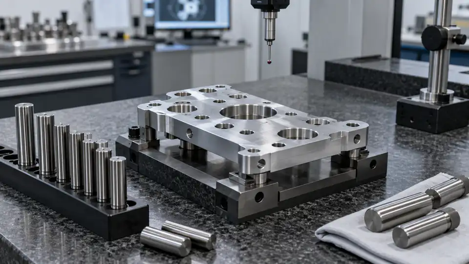
A hard gage can simulate a worst-case mating boundary and quickly confirm assembly-related requirements. For a hole pattern, fixed pins may represent the virtual-condition boundaries relative to datum simulators. If the part seats fully under the defined procedure, the gage can provide a practical attribute decision.
The gage design still requires engineering: gage tolerances, wear allowance, datum sequence, clamping force, insertion direction, projected height, temperature, calibration, and handling must be documented. A gage that forces a flexible part into compliance can mask a failure; a gage that does not represent the actual datum contacts can reject usable parts.
Inspecting with a CMM
A CMM can report actual size, location, orientation, bonus, and datum mobility numerically. It is useful for first articles, process diagnosis, and records. The program must implement the same standard edition, feature association method, datum simulators, modifiers, and simultaneous-requirement rules intended by the drawing.
Ask the inspection provider to identify software version, probe strategy, point distribution, filters, fitting algorithms, alignment construction, and reporting convention for critical characteristics. A high point count cannot rescue an incorrect datum model. Correlate the CMM program with a functional gage or known reference when the assembly boundary is important.
Manual Inspection Has Limits
Pins, height gages, surface plates, indicators, bore gages, and sine equipment can support some material-condition evaluations. However, manually adding a two-point size result to an independently measured center offset may not reproduce the standard’s required envelopes or datum behavior.
Use manual methods only when the characteristic, uncertainty, access, and decision rule are understood. For low-risk features, a documented open setup may be adequate. For dense patterns, compound datums, flexible parts, or very small tolerance, qualified CMM or functional-gage methods are usually more repeatable.
Threaded and Splined Features Need Special Care
Threaded holes and studs are functionally features of size, but their mating boundary relates to pitch diameter, thread form, lead, angle, and fastener flexibility—not simply the drilled minor diameter. ISO’s public explanatory material warns that applying its MMR/LMR tools to threaded features can be risky because ISO 2692 does not define those rules for threads.
When a threaded pattern has position at MMC, follow the governing standard and the organization’s validated practice. State whether the requirement applies to the pitch cylinder and whether a projected zone represents the engaged fastener length. Do not calculate bonus from the tap-drill measurement unless the specification explicitly makes that the controlled feature.
Projected Tolerance Zones Change the Assembly Model
A threaded hole can guide a long fastener above the surface. Position measured only within the part thickness may not limit angular error enough to prevent interference with a remote mating plate. A projected tolerance zone extends the controlled zone above the surface for a stated height.
The supplier needs the projection height, direction, datum reference, and inspection plan. CMM evaluation may construct the hole axis and project its deviation; a functional gage may use pins of the specified length. Include the method in the RFQ when assembly risk is high.
Composite Position Requires More Than a Bonus Calculation
Composite position can control a pattern’s location to datums in the upper segment and refine feature-to-feature orientation or spacing in the lower segment. Material-condition modifiers interact with each segment according to the governing rules. Treating the callout as one tolerance plus one bonus can give the wrong answer.
For quotation, provide the full feature-control frame and basic dimensions. Ask whether the supplier’s CMM software and inspection staff can evaluate the exact composite structure. A ballooned report should distinguish segments and identify any datum mobility used.
Flexible Parts Can Defeat a Simple Boundary Check
Thin plates, plastic housings, and sheet-like machined parts can change shape under gravity or clamping. A functional gage may restrain them differently from the assembly, while a CMM free-state result may not represent installed function. The drawing should state restraint conditions where the standard and design require them.
Agree on support points, clamp force, sequence, temperature, and stabilization time. Bonus tolerance cannot compensate for an undefined part state. If the mating assembly intentionally straightens the component, use a qualified restraint method that reproduces that interface without concealing local damage or size error.
Coatings and Heat Treatment Affect Material Boundaries
Anodizing, plating, conversion coating, heat treatment, and passivation can change size, form, or measurement behavior. State whether size limits and geometric controls apply before or after treatment. For a plated external pin, added thickness moves the feature toward MMC; for a coated hole, buildup can reduce the opening.
Supplier quotes should include masking, pre-process allowance, post-process inspection, and any correction plan. If the functional boundary applies in the final condition, evidence taken before coating alone is not sufficient.
Do Not Mix ASME and ISO Defaults
ASME Y14.5 and ISO GPS standards share familiar terms but differ in defaults, terminology, specification principles, and some interpretations. A drawing should state its governing standard and edition. Purchase documents should not supplement it with isolated rules from another system unless the design authority formally defines the combined requirement.
ISO 2692:2021 defines maximum material requirement, least material requirement, and reciprocity requirement for cylindrical features of size and two opposed parallel planes. ASME’s current Y14.5 material and training resources address MMC, LMC, RFS, boundaries, datum feature simulators, and functional gaging within the ASME framework. Use licensed standards and qualified review for the released drawing.
Build an Inspection Record That Can Be Recalculated
A useful variable report records more than “position PASS.” Capture the size limits, actual evaluated size, material condition, stated geometric tolerance, calculated bonus, total allowable tolerance, actual geometric result, datum setup, any datum mobility, units, part state, program revision, and disposition.
| Report field | Why it matters |
|---|---|
| Drawing number, revision, and standard edition | Fixes the interpretation baseline |
| Feature and balloon number | Connects result to the controlled geometry |
| Size limits and actual mating size | Supports the bonus calculation |
| Stated tolerance and modifier | Shows the base geometric requirement |
| Bonus and total available tolerance | Makes acceptance arithmetic reviewable |
| Actual position/orientation result | Preserves measured performance |
| Datum simulator and mobility used | Explains reference-frame construction |
| Instrument, program, date, and part state | Supports traceability and repeatability |
For attribute gaging, record gage ID, calibration status, revision, inspection frequency, seating rule, and result. Preserve variable first-article data when it helps establish process centering rather than relying only on later go/no-go checks.
Common Drawing and RFQ Errors
- Applying MMC to a surface that is not a qualifying feature of size.
- Reversing the MMC limit for a hole and a pin.
- Adding bonus to the size tolerance rather than the geometric tolerance.
- Treating datum shift as though it were controlled-feature bonus.
- Ignoring form or using an incompatible actual-size algorithm.
- Calculating threaded-hole bonus from the minor diameter.
- Omitting the drawing standard and edition.
- Using a projected zone without its height or direction.
- Requiring a CMM report without specifying the expected evaluation.
- Accepting a functional gage that does not reproduce datum sequence or assembly restraint.
Each error can change acceptance even when the printed values remain unchanged. Resolve interpretation before machining begins.
What the Buyer Should Send for Quotation
Provide the native or neutral 3D model, a controlled 2D drawing, part and revision identifiers, material and final condition, quantity, and delivery requirements. The drawing should contain the full feature-control frames, basic dimensions, datum features, size limits, and governing standard.
For critical material-boundary controls, also include:
- The functional mating condition or minimum-material risk being protected.
- Required inspection method or permission for the supplier to propose one.
- Whether variable results, attribute results, or both are required.
- Final process state, restraint, temperature, and sampling expectations.
- Gage ownership, qualification, calibration, maintenance, and acceptance authority.
- Rules for deviations and drawing-interpretation questions.
This information lets suppliers quote comparable engineering, tooling, inspection, and documentation scope.
Questions to Ask Before Award
- Which actual-size definition will your inspection method use?
- How will the datum reference frame and any material boundary be simulated?
- How will controlled-feature bonus and datum mobility appear in the report?
- Can your software evaluate the drawing’s standard edition and composite frames?
- Will a functional gage be used, and how will it be qualified?
- What operations can move size toward MMC after in-process inspection?
- How are coating, heat treatment, restraint, and temperature handled?
- What is checked on the first article and what is sampled in production?
- Who resolves a disagreement between the CMM and the gage?
- Are inspection-program changes revision-controlled?
Require written assumptions in the quotation. Silence is not proof that the supplier interpreted the modifiers as intended.
A Practical Release Checklist
- Confirm every modifier is applied to an eligible feature and serves a functional purpose.
- Calculate MMC, LMC, and the fixed boundary for internal and external features independently.
- Test the worst-case assembly or minimum-wall condition.
- Verify that size limits, form controls, and geometric controls work together.
- Specify the standard and edition without mixing default rules.
- Review datum sequence, datum feature simulators, and permitted mobility.
- Define actual-size algorithms and inspection state for critical features.
- Validate projected zones, composite controls, and pattern requirements.
- Account for coating, heat treatment, flexibility, and temperature.
- Choose a CMM, functional gage, or manual method that matches the decision.
- Make reports show actual size, bonus, total tolerance, result, and datums.
- Freeze the drawing, model, inspection program, and gage revisions at release.
The Practical Decision
Use MMC when the worst-case mating boundary governs assembly and additional clearance can safely permit more geometric variation. Use LMC when the limiting function is the amount of material that must remain, such as a wall or ligament. Use RFS when the geometry must remain within a constant tolerance throughout the size range or when size-dependent relief would not protect function.
The central rule is simple: the modifier should model a real boundary, and the inspection method should reproduce that same boundary. Calculate size departure explicitly, keep datum mobility separate, and require records another engineer can recalculate. That turns material-condition notation from a drawing shortcut into an auditable manufacturing requirement.
For a technical review of a CNC drawing before quotation, send the 3D model and controlled 2D drawing through Request a Quote. QuickCNCs can review the feature-control frames, manufacturing route, and proposed inspection evidence before production release.