
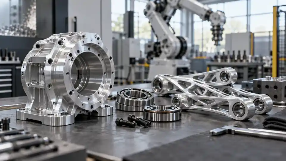
Robot-arm joints and lightweight links are not ordinary machined brackets. A small error at a bearing bore can tilt an axis; a flexible link can amplify servo correction; an unsuitable coating allowance can close a fit that was correct at the machine. The manufacturing decision therefore begins with the robot’s load path, motion envelope, accuracy target, duty cycle, and assembly sequence—not with a general request for “tight tolerances.”
This robot arm joint CNC machining decision guide explains when subtractive manufacturing is the right route, which interfaces deserve the tolerance budget, how to keep mass low without sacrificing stiffness, and what evidence a buyer should request before production. Numerical limits must come from the released design and system model. The examples below show a method for making those choices; they are not universal robot specifications.
When CNC Machining Is the Right Manufacturing Route
CNC machining is a strong choice when the joint or link has several precise interfaces that must remain related in one coordinate system. Typical examples include coaxial bearing seats, a reducer pilot, a motor register, dowel holes, an encoder mount, and attachment faces. Machining those features in coordinated setups can reduce the number of separately fabricated pieces and the alignment stack between them.
Machining also suits development and bridge production. Geometry can change without committing to a die or dedicated mold, and a supplier can revise pockets, cable passages, or interfaces while retaining the same functional datums. It is especially useful when annual volume is modest, the component has many variants, or the cost of misalignment is much larger than the material removed.
Another route may be better when the part is a simple constant-section link, a very large thin shell, or a high-volume near-net-shape component. Extrusion, tube fabrication, sheet-metal construction, casting, forging, or additive manufacturing can reduce waste or enable shapes that are expensive to cut. A hybrid route is common: obtain an extrusion, forging, or casting near the final envelope, then machine the critical joint interfaces.
Use a route comparison that includes tooling, qualification, scrap exposure, design-change cost, inspection, and the transition to volume—not only unit machining price.
| Part condition | CNC machining is attractive when | Consider another route when |
|---|---|---|
| Joint housing | Several bearing, motor, reducer, and encoder interfaces must be aligned | Very high volume justifies a qualified casting or forging |
| Lightweight link | End interfaces, cable paths, and local stiffness features change during development | A straight tube or extrusion meets the load and envelope |
| Wrist component | Five-axis access can consolidate complex faces and angled features | Internal channels cannot be reached and additive production is mature |
| Large arm section | Critical end datums can be finish-machined after fabrication | Removing most of a large billet creates excessive time and distortion risk |
Translate Robot Performance into Component Requirements
The drawing should connect part characteristics to system behavior. Payload, reach, acceleration, emergency-stop loading, gearbox reaction, cable forces, and gravity create the structural load cases. Accuracy and repeatability targets then determine how much deflection, joint-axis error, backlash, and thermal drift the component can contribute.
Do not divide the system accuracy target equally among every dimension. Build a sensitivity model or tolerance stack. A few characteristics usually dominate:
- coaxiality or position between paired bearing seats;
- perpendicularity of the bearing axis to the mounting interface;
- runout of reducer, motor, brake, or encoder pilots;
- location of dowels that transfer alignment between assemblies;
- thickness or parallelism that sets bearing preload or gear mesh;
- stiffness of the load path between adjacent joint axes.
Dimensions that merely clear a cover, route a noncritical cable, or reduce mass may accept wider limits. This selective approach improves both cost and manufacturability. It also gives the supplier room to select tools and setups without weakening the robot’s functional geometry.
Establish a Functional Datum System
A datum scheme for a robot joint should represent how the part locates in the final assembly. For a rotary joint housing, a primary mounting face may establish axial seating, a bearing or reducer pilot may establish the rotation axis, and a clocking feature may establish angular orientation. Another design may legitimately reverse that order. What matters is that the selected sequence mirrors constraint in the assembled mechanism.
Avoid datums chosen only because they are easy to probe. A raw outside wall or cosmetic surface may be convenient in inspection but irrelevant to motion. If the CMM aligns to that surface, the report can look stable while the joint axis is misplaced relative to the actual mounting interface.
The RFQ package should answer four questions:
- Which features establish the component coordinate frame?
- In what material or assembled condition are those features evaluated?
- Which interfaces are used to assemble the next link, gearbox, motor, and sensor?
- How are datum targets or simulators implemented during inspection?
For complex joint geometry, include a datum sketch or annotated assembly section. A supplier can then propose a process datum for manufacturing while preserving traceability to the functional datum system.
Control Bearing Seats as a System
A bearing seat is defined by more than diameter. Its size controls fit, but roundness, cylindricity, surface texture, shoulder squareness, chamfer geometry, spacing, and coaxial relationship can affect performance. A correct diameter in a distorted or misaligned bore does not produce a correct bearing installation.
Paired bearing seats deserve particular care. If they are accessible from one direction, line boring or coordinated finish boring in one setup may reduce coaxial error. If geometry forces separate approaches, the supplier needs a reliable datum transfer and an inspection method that evaluates the common axis. The drawing should state the functional relationship without prescribing an unnecessary machine model.
Define the acceptance state. Thin housings can change shape when released from a fixture, after anodizing, or when bolts clamp them into the assembly. If the functional condition is bolted, the engineering team may need a controlled restraint or an assembly-level requirement. Any restrained inspection must define fastener pattern, torque or force, contact surfaces, and sequence so the result is reproducible.
Bearing fits should be based on the bearing manufacturer’s guidance and the real load case. Ring rotation relative to load, material, temperature, wall thickness, installation method, and desired preload all matter. Do not copy an H7 label from a different mechanism without checking those conditions.
Protect Joint-Axis Alignment Across Multiple Components
Robot axis alignment often crosses several parts: a base, housing, reducer, output flange, link, and adjacent joint. Each interface can introduce radial location, angular tilt, face runout, and axial stack. The component drawing should control the contributors it actually owns, while an assembly drawing or interface-control document owns the combined condition.
Dowel pins can improve repeatable location, but only if hole fit, position, installation sequence, and service removal are understood. Bolts mainly provide clamp load; clearance holes should not silently become precision locators. Pilots can locate concentric assemblies, yet long or duplicated pilots may overconstrain the stack.
During supplier review, trace every alignment-critical relationship from the CAD model to machining, inspection, and assembly. Ask where the feature is created, whether it can be completed in one setup, how the datum is recovered after reclamping, and what actual-value record closes acceptance.
Balance Stiffness, Mass, and Machinability
Reducing robot-arm mass can improve acceleration, actuator sizing, energy use, and dynamic response. But a light component that bends or vibrates can reduce path accuracy and settling performance. NIST work on robotic machining notes the importance of compliance and configuration-dependent dynamics in robot accuracy; the same physical principle makes link stiffness and joint stiffness design inputs, not cosmetic preferences.
Begin with load paths from bearings and reducer mounts to the adjacent interface. Preserve material where it carries bending, torsion, and local bearing loads. Remove material where it contributes little to section stiffness. Deep decorative pockets may add machining time and create thin floors without an equivalent system benefit.
Ribs can raise stiffness efficiently, but their transitions need machinable radii and tool access. Closed pockets may trap chips or coolant. Extremely thin webs can deflect under cutting force, spring after unclamping, and distort during anodizing. For a long link, wall variation and residual stress can matter more than the nominal wall dimension.
Provide the supplier with the stiffness-sensitive zones and permissible mass, not only a fully constrained machining recipe. That lets the shop propose stock form, roughing sequence, stress-relief strategy, sacrificial supports, or near-net material while the design owner protects the structural result.
Select Material and Temper for the Real Duty
Aluminum alloys are common for lightweight links and housings because they combine low density, machinability, and corrosion-protection options. The choice between 6061, 7075, or another alloy should follow strength, fatigue, toughness, corrosion, joining, coating, stock availability, and operating temperature. A high nominal yield strength is not automatically the best system choice.
Steel can suit compact joints, bearing cartridges, highly loaded shafts, and wear interfaces where stiffness or contact stress dominates mass. Titanium may serve weight-sensitive, corrosion-resistant applications, but material and machining costs are higher and galling or joining behavior must be managed. Engineering plastics can isolate electricity, reduce mass, or provide low-friction guides, although creep, moisture, thermal expansion, and thread retention require review.
State the exact alloy, product form, and temper on the released drawing. If alternate material is allowed for a prototype, identify which validation results must be repeated before that material enters production.
Design Pockets, Ribs, and Wall Thickness for Stable Machining
Tool access determines whether a lightweight design is efficient to machine. Internal corner radius should be compatible with practical end mills; a larger radius permits a stiffer tool and a faster, more stable cut. Deep narrow pockets drive long-reach tooling, multiple step-downs, chip evacuation work, and higher breakage risk.
Keep wall thickness reasonably uniform where the load model allows it. Abrupt changes concentrate both structural stress and machining distortion. A thin web connected to a heavy bearing boss can move as residual stress is released. Smooth transitions and staged roughing can help, but geometry remains the first control.
If both sides of a link are pocketed, consider how the part will be supported after the first side is opened. Include accessible clamping lands or temporary stock where possible. Discuss whether sacrificial tabs or a removable support are acceptable, and state where witness marks are prohibited.
Plan Cable and Hose Routing Without Weakening the Link
Cable routing competes with structural material and joint packaging. Passages should respect minimum bend radius, connector size, installation direction, moving sweep, abrasion protection, and service access. A passage that is large enough in CAD may still be impossible to machine or to use during assembly.
Cross-drilled holes and sharp pocket intersections can create stress concentrations. Blend transitions, avoid placing a cable channel through a peak bending zone without analysis, and check remaining ligament around fasteners and bearing seats. Where a channel passes near a precision bore, rough it before final boring so stress release occurs before the critical feature is finished.
Define protection at edges and exits. Edge breaks, grommets, liners, or separate guides may be necessary. If the component will be anodized, masked electrical bonds and abrasion zones must be explicit. Treat service replacement as part of the design: the cable should not require bearing removal unless that maintenance sequence is intentional.
Choose a Machining and Setup Strategy
Three-axis machining may be sufficient for planar links and accessible housings. Five-axis positioning can reduce refixturing for angled motor faces, intersecting bores, and wrist components, but five-axis capability alone does not guarantee alignment. The key is how the supplier establishes and verifies the functional coordinate system.
A typical joint-housing route may include:
- qualify material and establish traceability;
- rough the major cavities while retaining support;
- allow a stabilization step when material removal is severe;
- create functional datum faces and pilots;
- finish coordinated bearing and reducer interfaces;
- machine threads, cable features, and noncritical details;
- deburr and clean without damaging fits;
- inspect the pre-finish state;
- apply coating or other outside process;
- verify designated final-state characteristics.
This is a planning example, not a mandated route. The supplier remains responsible for proving that its process holds the drawing.
Account for Finishing Before the Tolerance Is Released
Anodizing, hard coating, plating, conversion coating, paint, or passivation can affect dimension, contact, friction, and appearance. For aluminum joints, coating growth may reduce bearing bores and alter pilot fits. Pretreatment can also remove material. Use the processor’s qualified pre/post relationship rather than a universal allowance.
Mask bearing seats, precision pilots, grounding locations, and thread features only when the functional requirement supports masking. A masked transition has its own boundary and corrosion considerations. If a bore is finished after coating, review whether exposed aluminum is acceptable and how chips and coolant will be removed.
Cosmetic expectations should be separated from structural and alignment requirements. Define viewing zones, color standard, gloss or texture reference, and permitted rack marks. A photograph sent by email is not a controlled color standard.
Inspect the Component in Its Functional State
Inspection planning should be agreed before award. A CMM can evaluate datum relationships, bore locations, face orientation, and profiles when probe access and datum simulation are suitable. Air gaging, bore gages, roundness equipment, surface-texture instruments, or dedicated fixtures may be better for particular characteristics.
For alignment-critical bores, request actual values rather than a pass/fail certificate alone. The report should identify part number, revision, serial or lot, characteristic, nominal, tolerance, actual result, unit, method, and date. If software constructs an axis from multiple circles or scans, agree on the evaluation method where different algorithms could change acceptance.
Measure free-state and restrained-state requirements as explicitly defined. Do not allow an unrecorded clamp to make a flexible part appear conforming. Temperature should also be considered for tight fits across dissimilar materials.
Validate the Joint, Not Only the Individual Part
Component inspection cannot detect every assembly interaction. Development validation may include bearing installation force, reducer seating, motor alignment, joint torque, backlash, encoder repeatability, cable sweep, thermal behavior, stiffness, vibration, and repeated disassembly. Select tests from system risk rather than using the same checklist for every joint.
First-article review should compare the measured component with functional test results. If a joint passes dimensional inspection but shows high torque or poor repeatability, investigate datum simulation, bearing installation, surface condition, assembly preload, and interacting-part tolerances before simply tightening the drawing.
Record any approved design or process changes with effectivity. A successful prototype made from different material, in a different finish condition, or with hand fitting does not automatically qualify the production configuration.
What to Include in the RFQ Package
A quote-ready package for a robot joint or link should contain:
- the native CAD file when useful, a neutral 3D model, and a controlled 2D drawing;
- part number, revision, and a clear conflict-authority rule;
- alloy, temper, product form, and required material records;
- annual volume, lot size, prototype quantity, and delivery phases;
- functional datum scheme and critical interfaces;
- bearing, reducer, motor, encoder, brake, dowel, and fastener requirements;
- coating, masking, color, rack-mark, and final-dimension requirements;
- inspection deliverables and any first-article or capability expectations;
- cleanliness, packaging, identification, and traceability requirements;
- assembly or validation information needed to understand the load path.
Ask bidders to list exceptions and assumptions. A low quote based on a missed finishing allowance or unpriced inspection plan is not comparable with a complete offer.
Questions to Ask a CNC Supplier
Ask how the shop will relate paired bearing seats, mounting faces, and reducer pilots. Request a route sketch rather than a generic capability statement. The answer should show where functional datums are established, which features share a setup, and how alignment is recovered after reclamping.
Ask how thin sections will be supported and how free-state geometry will be protected. Discuss roughing balance, stock condition, stabilization, tool access, and coating sequence. For a near-net blank, ask how variation in the incoming form is located relative to finish machining.
Ask which measurements will be supplied as actual values and which are sampled. Confirm that the method can reach deep bores and complex interfaces. Finally, ask which outside processes are subcontracted and how revision, lot identity, nonconformance, and final records flow through those suppliers.
Prototype, Bridge, and Production Decisions
For an early prototype, machining from billet may offer the quickest controlled route and the most freedom to revise geometry. The prototype plan should still record deviations, manual fitting, and temporary materials so that success is not attributed to an unreproducible configuration.
Bridge production tests repeatability. Freeze the datum strategy, stock form, coating route, inspection method, and assembly sequence before judging capability. Review actual values across the lot, not just the first conforming unit.
At higher volume, compare a near-net process plus finish machining against continued billet machining. Include tooling amortization, material yield, qualification lead time, engineering changes, maintenance, and failure cost. Keep finish machining on the alignment-critical interfaces unless the alternative process has demonstrated equivalent capability.
Common Failure Modes and Corrective Actions
Bearing fits are correct before anodize but tight afterward
Confirm coating type, thickness, pretreatment, masking, and measured pre/post change. Correct the process allowance or mask boundary; do not ream every finished bore without engineering approval.
Paired bores pass size but the joint binds
Evaluate common-axis alignment, shoulder orientation, bearing installation, housing restraint, and interacting parts. Diameter data alone is incomplete.
A lightweight link springs after unclamping
Review stock condition, material-removal balance, setup forces, wall transitions, roughing sequence, and free-state inspection. Redesign may be more robust than adding another finish pass.
Cable installation damages the harness
Check bend radius, edge condition, connector path, coating roughness, and service sequence. Modify the passage or add controlled protection before production.
Repeatability changes after supplier transfer
Requalify datum simulation, setups, finish allowance, assembly interfaces, and actual-value inspection. A transferred CAD file is not a transferred manufacturing process.
Final Sourcing Checklist
Before releasing a robot-arm joint or lightweight link, verify that:
- system loads and performance targets are translated to component characteristics;
- functional datums represent the assembled constraint;
- bearing seats include geometry, texture, shoulder, and alignment controls;
- the stiffness-to-mass decision is supported by analysis or testing;
- cable routes are machinable, structurally acceptable, and serviceable;
- stock form, material condition, and coating are fully specified;
- critical dimensions name their pre- or post-finish state;
- the supplier has a credible setup and datum-transfer plan;
- inspection methods return usable actual values;
- prototype deviations are not carried silently into production;
- the quote identifies assumptions, outside processes, and qualification work.
Make the Route Decision from the Functional Interfaces
CNC machining is most valuable for robot joints when it consolidates related precision interfaces and supports rapid design change. It does not remove the need for system engineering. The buyer still has to identify the load path, datum structure, alignment budget, final finish state, and evidence required to accept the component.
For an actionable review, send the 3D model together with the controlled 2D drawing, quantities, material condition, finishing requirements, and assembly context. QuickCNCs can then assess tool access, workholding, critical-interface strategy, inspection, and the practical route through its CNC milling services or rapid prototyping workflow. For a production quotation, use the Request a Quote page.
References
- NIST Robotics — measurement science and performance considerations for robotic systems.
- NIST Accurate Robotic Machining — discussion of compliance, configuration, and machining accuracy.
- NIST Dimensional Metrology — traceability and dimensional-measurement resources.