
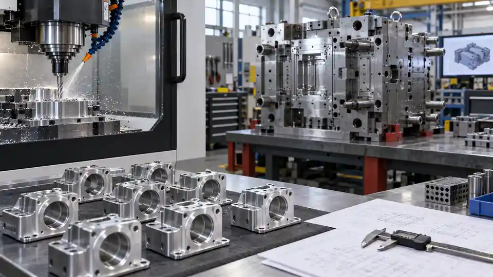
Bridge production uses an interim manufacturing route to supply usable parts while the intended high-volume process or hard tooling is being developed, qualified, repaired, or transferred. CNC machining is often selected because it can start without mold, die, casting, or forging tooling and can respond to design changes. The benefit is time; the risk is allowing temporary assumptions to become an uncontrolled production system.
This CNC bridge production guide explains how to define volume, product equivalence, fixtures, inspection, finishing, cost, change control, capacity, and exit criteria while hard tooling is built. It is intended for machined bridges to molding, casting, forging, stamping, extrusion, or automated production, as well as temporary CNC capacity during a tool transfer.
Define Why the Bridge Exists
A bridge should have a specific business and engineering purpose. Examples include:
- supplying pilot or validation units before hard tooling is ready;
- supporting early customers during a launch;
- replacing output while a damaged tool is repaired;
- covering a supplier transfer or second-source qualification;
- meeting a short demand spike that does not justify new hard tooling;
- allowing design learning before locking tooling; or
- protecting service/spare demand after the production tool retires.
Record the start trigger, target quantities, required delivery window, and planned end condition. “Temporary until production starts” is not enough. The organization needs to know what event authorizes the bridge and what evidence closes it.
Compare the Interim and Production Routes
The same nominal geometry can behave differently when machined from billet rather than molded, cast, forged, or stamped. Build a route-difference matrix before treating bridge units as equivalent.
| Attribute | CNC bridge route | Intended hard-tool route | Decision required |
|---|---|---|---|
| Material form | Plate, bar, billet, near-net blank | Molded resin, casting, forging, sheet | Are properties and certifications comparable? |
| Grain/fiber flow | Wrought stock direction or isotropic plastic assumption | Forged flow, molded fiber orientation, cast structure | Which strength/warpage tests transfer? |
| Wall/draft | Machined walls; draft optional | Draft and process-driven wall rules | Will bridge geometry match final interfaces only or full form? |
| Internal features | Tool-access and cutter-radius limits | Cores, slides, formed details | Are redesigns temporary or permanent? |
| Surface | Machining marks plus secondary finish | Mold/die/cast texture and defects | What appearance/tribology evidence transfers? |
| Residual stress | Stock and machining redistribution | Cooling, forming, casting, or forging stress | Is flatness or stability comparable? |
| Tolerance pattern | CNC process variation | Tool/process-specific variation | Can validation results be applied to production? |
| Unit cost | Higher variable machining cost | Tool amortization plus lower recurring cost | What is the break-even and exposure? |
Classify each requirement as equivalent, conservative, nonrepresentative, or unknown. That classification controls testing and customer disclosure.
Set Product Equivalence Deliberately
Bridge parts may be form-fit-function equivalent, interface equivalent, test representative, or commercial-use approved. These are not interchangeable labels.
For each critical characteristic, state:
- production requirement;
- bridge implementation;
- known difference;
- functional effect;
- inspection or test needed;
- approval authority; and
- later production-tool validation that remains required.
A machined aluminum cover can match interfaces and stiffness but may not reproduce die-cast porosity or production texture. A machined polymer housing may match dimensions but not molded fiber orientation, knit lines, or long-term stress. Do not imply full equivalence from a passing assembly.
Freeze the Bridge Configuration
Bridge production begins early, when designs are still changing. Use clear configuration identity from the first order:
- part number and bridge suffix if appropriate;
- model and drawing revision;
- material and condition;
- interim deviations from production design;
- manufacturing route;
- finish and masking;
- inspection plan revision;
- packaging/labeling method; and
- lot or serial identity.
Avoid editing CNC files under the same name while parts are in progress. Apply effectivity to every change and reconcile WIP. If bridge and hard-tool parts coexist, packaging and enterprise systems must distinguish them where they are not fully interchangeable.
Decide Whether Geometry Should Match Production
Exact production geometry is useful when the bridge supports assembly, user evaluation, or tooling correlation. It may be inefficient or impossible when molding draft, undercuts, thin ribs, formed features, or cast texture are costly to machine.
Options include:
- machine exact final geometry;
- make a functionally equivalent CNC variant under an approved deviation;
- split and join components to reproduce inaccessible features;
- use a near-net blank plus machining;
- combine CNC with additive or fabricated features; or
- redesign a feature permanently for both routes.
Document what differs. A bridge-only relief, fillet, split line, fastener, or insert should not silently migrate into the production definition.
Select Material for Transferable Evidence
Use production material when material behavior affects the decision and the form is available. When it is not, compare chemistry, condition, product form, modulus, yield, fatigue, creep, thermal expansion, conductivity, corrosion, wear, and finish response.
A bridge material can be intentionally conservative for one attribute and nonconservative for another. Greater strength does not guarantee representative stiffness or thermal behavior. Machined solid plastic may differ significantly from an injection-molded glass-filled grade.
Record substitutions on the drawing or controlled deviation and on test reports. State which verification must be repeated on hard-tool parts.
Plan CNC Fixtures for the Volume Window
Bridge workholding should match quantity and schedule. Soft jaws and modular fixtures can start quickly but create more setups and operator dependency. Dedicated multi-part fixtures reduce cycle time and variation but add nonrecurring cost and change exposure.
Estimate expected total pieces, batch sizes, revision stability, machine count, and reuse. Then select:
- vise/soft-jaw workholding for very low volume and changing designs;
- modular plates and quick-change elements for mixed revisions;
- dedicated fixtures for stable higher bridge volume;
- palletized or tombstone systems for repeat cadence; or
- automation only when material loading, chip control, tool life, and schedule justify it.
Design fixture datum transfer around functional features. Include access for probing, deburring, and inspection. Identify fixture ownership, maintenance, storage, and disposition after bridge exit.
Model Total Bridge Capacity
Calculate demand by week or month, not annual average. Convert quantity into setup, machining, inspection, finishing, and release load. Account for learning, yield, maintenance, design-change stops, and peak demand.
The bridge supplier’s available hours must be net of existing commitments. Inspect bottlenecks beyond spindle time: programmers, fixture builders, large CMMs, deburring, cleaning, anodizing, heat treatment, and customer approval.
If the plan relies on several machines, confirm program/fixture compatibility and qualification. Adding a machine after a missed forecast may require more time than the recovery window.
Build the Ramp Schedule Backward
Start with the first required delivery and work backward through customer approval, final inspection, finishing, machining, material receipt, fixture prove-out, programming, DFM, and design release.
Include decision points:
- RFQ and route approval;
- controlled bridge design release;
- material and long-lead tool commitment;
- fixture design freeze;
- first-article completion;
- pilot lot and rate check;
- regular bridge production;
- hard-tool sample availability;
- production-tool validation; and
- final bridge order and closure.
Show dependencies between routes. Engineering resources may be shared between bridge changes and tool validation. A late production-tool sample can extend the bridge and consume material or capacity not originally reserved.
Define Inspection for the Interim Process
Bridge inspection should protect product function and produce evidence appropriate to use. It does not need every control of mature high-volume production, but it must address the risks created by the CNC route.
Use a ballooned drawing or characteristic list with:
- critical/interface dimensions;
- datum and alignment scheme;
- material/condition evidence;
- final surface and coating state;
- actual-value reporting where needed;
- sampling or 100% checks;
- first-article and post-change verification;
- functional/leak/pressure test; and
- traceability to lot or serial.
Do not use good bridge capability as proof of hard-tool capability. The variation mechanisms differ. Retain measurements that can support dimensional correlation when tool samples arrive.
Control Surface Finish and Secondary Operations
Bridge parts often need the production appearance or corrosion protection. Anodize, plating, passivation, heat treatment, painting, grinding, and cleaning can dominate lead time.
Confirm:
- process specification, type/class, and revision;
- dimensional growth or removal;
- masking and contact points;
- cosmetic zones and allowed rack marks;
- approved processor requirements;
- batch cadence and minimum charge;
- first-article or sample approval; and
- certificate/test documentation.
If the bridge finish is only a visual substitute, label it. Do not use it to claim production corrosion, wear, electrical, or biocompatibility performance.
Manage Design Changes Without Scrapping the Bridge
Early learning creates changes. Set a release calendar or cut-off that balances responsiveness with WIP stability. Before implementing a new revision, identify raw material, programs, fixtures, in-process parts, finished inventory, outside-process lots, and shipments.
Classify each change:
- safety or functional correction requiring immediate stop;
- interface change with controlled effectivity;
- cost/DFM change that can wait for the next batch;
- cosmetic change with sample approval; or
- production-tool-only change that does not affect bridge units.
Record disposition and approval. Do not let the bridge supplier absorb change cost invisibly; separate engineering, scrap, rework, and schedule impact.
Coordinate Bridge and Hard-Tool Suppliers
The interim and production sources need a controlled interface even if they are competitors. The product owner should control shared design data, approved changes, measurement definitions, and lessons learned.
Transfer useful information:
- critical interfaces and failure modes;
- bridge deviations and temporary features;
- dimensional results and assembly observations;
- finish/color samples and acceptance criteria;
- test methods and fixtures;
- design changes with effectivity; and
- unresolved risks for production tooling.
Do not force CNC process settings onto molding, casting, forging, or stamping. Transfer product requirements and relevant evidence, then allow the production specialist to develop its process.
Correlate the First Hard-Tool Parts
When production-tool samples arrive, compare them with the controlled bridge baseline. Use the same datum interpretation, interface measurements, assembly, and functional tests where appropriate.
Focus on route-dependent differences: shrinkage, warpage, porosity, draft, parting line, flash, fiber or grain direction, surface texture, coating response, residual stress, and tool-to-tool variation.
If a production sample fails while the bridge passed, do not assume the tool is wrong without checking equivalence. The bridge may have hidden the relevant process behavior. Update design, tool, acceptance method, or bridge claim based on evidence.
Decide Whether Bridge Parts Are Saleable
Some bridge parts are for internal testing only; others may ship to customers. Make that decision explicitly with engineering, quality, regulatory, and commercial owners.
Consider:
- product requirements and intended use;
- differences from approved production design/process;
- required validation and regulatory status;
- labeling and customer disclosure;
- service, warranty, and interchangeability;
- serial/lot traceability;
- spare parts and future replacement; and
- field-action or containment capability.
An approved prototype is not automatically a saleable bridge unit. Follow the organization’s release process.
Calculate Total Cost and Break-Even
Bridge cost includes more than unit machining. Model:
- DFM, programming, and process engineering;
- fixture, jaws, gages, and test equipment;
- material minimums and yield;
- setup and cycle time;
- inspection and documentation;
- secondary processing;
- expediting and split shipments;
- design-change rework/scrap;
- capacity reservation;
- packaging and logistics;
- supplier management; and
- closeout and tool disposition.
Compare cumulative bridge cost with accelerated hard tooling, soft/interim tooling, additive or fabricated routes, and lost-revenue/line-stop consequences. Break-even depends on time and risk, not only per-part price.
Bridge Cost and Risk Table
| Decision | Lower upfront option | Higher-control option | Trigger to upgrade |
|---|---|---|---|
| Workholding | Soft jaws/modular setup | Dedicated multi-part fixture | Stable volume and repeated setups |
| Inspection | Critical-feature plan | Broader actual-value/automated plan | Customer release or rising volume |
| Material | Available justified substitute | Production grade/form/traceability | Performance or regulatory dependence |
| Finish | Visual substitute | Production-intent process | Functional finish or saleable units |
| Capacity | Spot scheduling | Reserved cell/material/sub-tier slots | Firm ramp or line-stop consequence |
| Traceability | Batch identity | Serial-level configuration | Mixed revisions or field/service risk |
| Redundancy | Single qualified route | Backup machine/source qualification | Long bridge or severe interruption cost |
Monitor the Bridge Weekly
Track measures that predict delivery and exit:
- firm and forecast demand;
- material coverage;
- constrained-resource load;
- WIP by revision and operation;
- first-pass yield and open quality holds;
- outside-process queue;
- on-time delivery;
- design changes and pending approvals;
- remaining bridge quantity/cost; and
- hard-tool milestones and risks.
Review trends and actions, not dashboard color alone. A bridge can be on time today while consuming all reserved material and having no capacity for next month’s peak.
Control Packaging and Logistics During the Transition
Bridge lots are often smaller and shipped more frequently than mature production. This changes packaging labor, freight cost, export documents, and damage exposure. Define pack quantity, separators, corrosion protection, cleanliness, labels, reusable dunnage, and return logistics for the actual cadence.
If production packaging is not ready, approve an interim method against the same product risks. Machined cosmetic parts may need individual protection; precision sealing lands need caps or noncontact separators; clean parts may need double bags or controlled materials. A substitute foam or paper can transfer particles, moisture, or impressions.
Labels should identify the bridge configuration, part/revision, quantity, lot/serial, purchase order, and any customer-required status. When bridge and hard-tool units coexist, ensure receiving and assembly systems recognize the distinction. Do not rely on carton color alone.
Model transit and customs time separately from machining lead time. Frequent expedited air shipments can dominate total bridge cost. Set consolidation and priority rules, then retain enough local buffer for predictable transport variation.
Respond to a Bridge Quality Escape
Define containment before the first delivery. If a defect is found, identify affected revision, material lot, work orders, process period, finished stock, in-transit product, and customer locations. Bridge production changes frequently, so date-only containment can be too broad or too narrow.
Protect supply while investigating. Options may include sorted inventory, additional inspection, temporary process checks, approved rework, alternate units, or a controlled stop. Customer approval is required for deviations from product requirements.
Root-cause analysis should examine the interim route rather than assuming the future tool will eliminate the problem. A fixture shift, tool-wear rule, drawing ambiguity, finishing buildup, or manual blend may affect remaining bridge lots. Correct process documents and verify the first effective output.
Feed lessons into hard-tool design and validation when they reveal product sensitivity. Do not transfer CNC-specific corrective action as a mandatory molding or casting method; transfer the requirement, failure mechanism, and evidence.
Consider Alternatives to a Fully Machined Bridge
CNC from billet is flexible but may not be the lowest-risk bridge at higher volume or complex geometry. Compare:
- soft or prototype tooling;
- urethane casting or silicone molds;
- additive manufacture with secondary machining;
- laser/waterjet-cut and fabricated assemblies;
- extrusion or near-net stock with machining;
- temporary casting patterns;
- sheet-metal forms; and
- hybrid routes using purchased inserts or standard components.
Evaluate each against start date, per-unit rate, material behavior, geometry, tolerance, finish, inspection, quantity ceiling, change flexibility, and evidence transfer. A hybrid route may shorten cycle time while preserving critical machined interfaces.
Do not select solely on unit price. A method that needs customer revalidation after every change or cannot meet the peak rate may cost more in elapsed time and program risk.
Example: Housing Before Die-Cast Tool Approval
Consider a housing planned for die casting and finish machining. Early systems need units before the die is complete. A CNC bridge uses 6061 plate with the production interfaces, sealing land, bearing bores, and connector openings. Nonfunctional casting ribs and draft are simplified under an approved bridge drawing.
The team identifies which tests transfer. Assembly fit, bearing alignment, connector access, and basic thermal tests may be meaningful. Die-cast porosity, production residual stress, texture, wall variation, and casting-process capability remain open. The anodized bridge finish supports corrosion handling and appearance direction but is not the future conversion coating on the casting.
Demand increases from 20 to 80 units per week. The original soft-jaw process cannot meet the peak with inspection and finishing. Before the ramp, the supplier adds a dedicated multi-part fixture, verifies the updated program, runs a delta first article, and reserves an anodize slot. The commercial plan separates fixture cost from recurring price.
When die-cast samples arrive, the buyer measures the same datum interfaces and repeats route-dependent tests. Bridge output continues during tool correction, with distinct lot identity. Exit occurs only after tool approval, demonstrated rate, adequate buffer, and reconciliation of bridge material and fixtures. This example illustrates the control logic; it is not a claim about an actual QuickCNCs customer program.
Plan the Exit Before Starting
Define exit criteria such as:
- production tool approved against dimensional and functional requirements;
- rate and quality demonstrated;
- regulatory/customer release complete;
- safety stock established;
- open bridge orders reconciled;
- old/new configurations segregated;
- service and spare strategy decided;
- CNC fixtures/tools returned, stored, or disposed;
- obsolete data access removed; and
- final bridge records archived.
Specify an overlap period if needed. Dual production can protect supply while tool output stabilizes, but it needs clear allocation and configuration control.
Common Bridge Failures
Temporary geometry becomes undocumented product definition
A machining relief or bonded insert persists through customer builds without an approved deviation. Record every route-specific difference.
The bridge is sized to average demand
Peak launch requirements exceed spindle, inspection, or finishing capacity. Load the actual time-phased forecast.
Hard-tool delays are treated as free extension
Material, fixtures, and capacity were reserved only for the original window. Requote and replan before the bridge runs out.
Machined evidence is applied to the production process
Tests influenced by material form or route are not repeated. Identify nontransferable evidence in the validation plan.
Bridge and production parts mix
Labels and enterprise records show only the same base part number. Use controlled suffix, lot/serial, or route identity as required.
Tooling ownership is unclear
Customer-funded fixtures remain at the supplier without maintenance, access, or disposition terms. Establish an asset register.
Supplier RFQ Package
Provide:
- bridge purpose and approved use;
- controlled model/drawing and production-route context;
- route-specific deviations;
- time-phased quantities and upside;
- required first and last delivery;
- critical/interface characteristics;
- material and finish fidelity;
- inspection/test and documentation;
- design-change frequency and effectivity rules;
- tooling ownership and reuse expectations;
- capacity evidence and recovery needs; and
- transition and exit milestones.
Ask the bidder to state assumptions, constraint, net capacity, nonrecurring/recurring price, change policy, and extension terms.
Make the Bridge a Controlled Transition
A successful bridge does more than ship early parts. It preserves the right product configuration, provides evidence with clearly stated limits, maintains enough capacity through demand peaks, and exits when the production route is demonstrably ready.
NIST MEP’s product design and development resources connect prototyping with material selection, testing, manufacturing, and launch. Its supply-chain guidance also emphasizes mapping, risk assessment, supplier evaluation, and continuity—all relevant to a bridge spanning two routes.
For a QuickCNCs bridge-production RFQ, send the current model and drawing, route comparison, time-phased demand, required evidence, hard-tool milestones, and exit criteria. We can propose machining, workholding, inspection, and capacity assumptions while keeping the interim configuration and future validation boundary explicit.
Review the bridge against the capacity and lot assumptions on the low-volume CNC machining page and use CNC machining services to identify the production route. Submit the transition dates and exit gate through Request a Quote.