
Micron-level part tolerances can be achievable on selected features, but a machine specification is not a blanket promise for every material, geometry, setup, batch, or measurement method. A credible plan separates four questions: how an axis positions, how repeatably it returns, what size and form the finished part actually holds, and whether the inspection system can distinguish conforming from nonconforming parts.
Do not infer a part tolerance directly from encoder resolution or a positioning-repeatability value. The deliverable must be tied to a named feature, datum system, material and condition, process route, temperature, quantity, and agreed inspection method. Capability should be demonstrated with representative parts and measurement uncertainty appropriate to the acceptance decision.
For project planning, use the CNC tolerances and inspection page to define the drawing and evidence package before requesting a quotation.
What Are the Tolerances for CNC Machining, Generally Speaking?
There is no universal “standard CNC tolerance” that applies to every feature. An open length, a reamed hole, a bored diameter, flatness across a thin plate, true position after multiple setups, and surface finish all respond to different error sources. Larger parts, thin walls, long overhangs, difficult materials, heat treatment, coating, and repeated unclamping can widen the achievable process window.
Start with function. Apply tighter limits only to features that control fit, motion, sealing, alignment, fatigue, or another verified requirement. For each critical feature, specify the datum reference frame and whether the tolerance applies before or after heat treatment or finish. Over-tolerancing every dimension raises setup, tool-life, inspection, and scrap risk without necessarily improving function.
Part tolerance is a process result
- Machine contribution: geometric errors, axis positioning, spindle behavior, servo response, and thermal state.
- Cutting contribution: tool runout, deflection, wear, cutting force, chip evacuation, and heat.
- Workpiece contribution: residual stress, elastic recovery, clamping distortion, section changes, and material CTE.
- Setup contribution: datum transfer, probing, fixture repeatability, re-clamping, and operator method.
- Measurement contribution: calibration, resolution, sampling strategy, fixturing, temperature, surface condition, and uncertainty.
So, What is the Micron Tolerance of a CNC Machine Itself?
A machine tool does not have one “micron tolerance.” Manufacturers may report linear positioning accuracy, unidirectional or bidirectional repeatability, straightness, spindle runout, or volumetric performance under stated test conditions. These quantities are not interchangeable and do not equal the tolerance on a production part.
ISO 230-2 defines methods for evaluating the accuracy and repeatability of positioning of individual numerically controlled axes through repeated measurements at specified positions. That is a machine test. A finished part also includes tool, spindle, workholding, material, thermal, toolpath, and inspection effects.
Accuracy, repeatability, resolution, and tolerance
| Term | What it tells you | What it does not prove |
|---|---|---|
| Command or display resolution | Smallest programmed/displayed increment | That the axis physically moves that amount accurately |
| Positioning accuracy | Deviation between commanded and measured positions under a defined test | Finished-part size, form, or surface finish |
| Positioning repeatability | Spread when returning to test positions | Closeness to the target or multi-feature part capability |
| Part tolerance | Permitted variation of a specified feature | That a process is capable or that inspection uncertainty is adequate |
| Measurement uncertainty | Quantified doubt associated with the reported measurement | Automatic acceptance merely because the instrument has fine resolution |
Thermal state is especially important. HEIDENHAIN’s machine-tool guidance identifies thermal error as a major source of modern machine-tool positioning error. The related QuickCNCs article shows how to calculate and document thermal expansion without applying the result to the wrong feature.
When We Talk About Micro Machining, What Tolerances Are Expected?
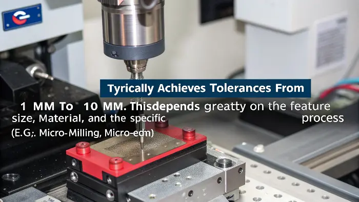
Micro-machining describes small tools, small features, or small workpieces; it does not create a universal ±1 µm to ±10 µm band. The achievable result depends on feature size and aspect ratio, tool diameter and runout, edge radius relative to chip thickness, material grain or fillers, burr formation, workholding, and the available metrology.
Define the feature and evidence before naming a number
A supplier should be able to answer: Which feature is controlled? Over what size and depth? Relative to which datums? In what material and condition? At what stage of manufacture? At what temperature? By what instrument and sampling plan? If those questions are unanswered, a single micron value is marketing language, not a manufacturing specification.
NIST’s review of dimensional metrology for micro/mesoscale manufacturing explains that uncertainty comes from the measurement device, environment, setup, and sampling. The inspection method must therefore be selected with the feature, not added after production.
Ultimately, What Is the Smallest Machining Tolerance Possible with CNC?
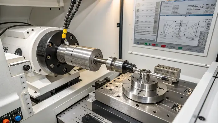
Ultra-precision processes can operate in the sub-micrometre domain on selected materials and features, but that does not establish a general CNC service capability. Diamond turning, precision grinding, lapping, honing, jig grinding, and controlled metrology may be different process routes with different surface, geometry, and material limits.
A defensible capability plan
- Freeze the definition: controlled drawing revision, 3D model, datum scheme, material/condition, quantity, finish, and measurement temperature.
- Select the route: reserve stock for finishing, separate roughing and stabilization when needed, minimize datum transfers, and plan heat treatment or coating explicitly.
- Control the process: qualify workholding, warm-up state, tool-life limits, compensation rules, and in-process checks on a representative feature.
- Prove measurement suitability: use calibrated equipment, a documented method, and uncertainty that supports the acceptance decision. NIST emphasizes that every dimensional measurement is an estimate with uncertainty.
- Demonstrate stability: review results across representative parts, positions, tools, setups, and time. One conforming feature does not prove batch capability.
QuickCNCs does not treat a nominal micron number as an unconditional service promise. For a critical RFQ, provide the functional tolerance, mating-part context, expected temperature range, quantity, and required report. The quality assurance page describes the documentation and inspection information to agree before production.
Conclusion
Micron-level tolerances are feature-specific engineering requirements, not a label attached to a machine. Separate axis positioning accuracy from repeatability, part tolerance, and measurement capability; then control material, workholding, tooling, process sequence, temperature, and inspection as one system. Quote and accept only the capability that the defined feature and evidence can support.