
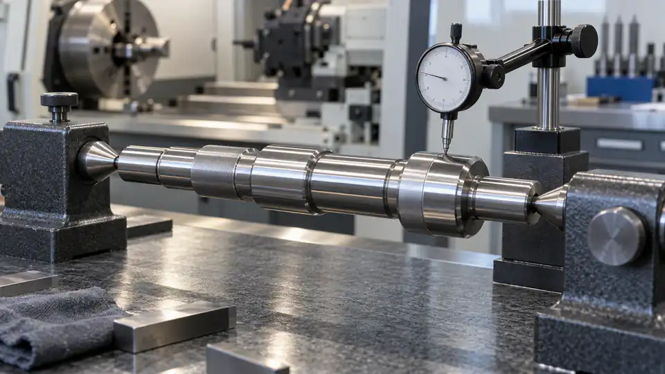
Circular runout is often added to a turned-part drawing when “concentric” is too vague, but the callout is useful only when the datum axis, controlled surface, section locations, and measurement setup represent the assembly. A bearing journal can meet diameter and still wobble relative to a mounting pilot; a face can be flat but show axial runout because it is not square to the rotation axis.
This circular runout CNC turned part guide explains the difference between circular and total runout, radial and axial applications, datum selection, manufacturing strategy, and inspection. Final interpretation must follow the drawing’s specified edition of ASME Y14.5 or ISO 1101 and the product’s qualified GD&T practice.
What Circular Runout Controls
Circular runout controls variation of individual circular elements as the part rotates about a datum axis. At each measured section, an indicator reading must remain within the stated tolerance under the applicable standard. On a cylindrical surface the indicator is normally oriented radially; on a face it is oriented to evaluate axial variation.
The result combines several possible contributors. Radial reading can reflect circularity of the section and its coaxial relationship to the datum axis. Face reading can reflect local flatness of the circular element and orientation to the axis. The indicator does not identify which geometric contributor caused the variation.
Use circular runout when performance is evaluated at particular circular sections during rotation and when controlling the combined behavior is more useful than separately specifying every contributor.
Circular Runout Versus Total Runout
Circular runout evaluates one circular element at a time. Total runout evaluates variation over the entire controlled surface while the part rotates and the indicator traverses that surface. On a cylinder, total runout adds control across length and can restrict straightness, taper, and overall coaxial behavior more comprehensively. On a face, it controls the full surface as the indicator sweeps radially.
| Design need | Circular runout | Total runout |
|---|---|---|
| Variation at selected cross-sections | Directly suited | Included within broader control |
| Entire bearing journal over length | May need several defined sections | Often clearer when full surface matters |
| Local face track at a seal diameter | Useful | Use when whole annular face must be controlled |
| Long shaft taper or bow | Does not fully control between sections | Better combined full-surface control |
| Cost and inspection time | Usually fewer readings | More traversal and data |
Do not choose total runout automatically because it sounds more complete. Apply the least restrictive control that protects function.
Radial Versus Axial Runout
Radial runout is measured with the sensor sensitive to radial displacement, commonly on a cylindrical journal, pilot, outside diameter, or rotating sealing surface. Axial or face runout is measured along the axis direction on a face, flange, shoulder, or annular land.
For a flange mounted on a shaft, both may matter: radial runout of the pilot affects concentric location, while face runout affects tilt or axial wobble. State separate controls and datum references as needed.
Avoid the vague note “TIR” without a feature-control frame, surface, datum, direction, and location. TIR is also used colloquially for total indicator reading, which does not itself define the GD&T requirement.
Select the Datum Axis from Function
The datum feature should be the interface that establishes the part’s rotation in assembly. It may be a bearing journal, center hole pair, bore, pilot, tapered seat, or a common datum created from multiple features. The resulting datum axis must be reproducible in manufacturing and inspection.
Do not select the largest outside diameter only because it is easy to chuck. If the part rotates on bearings located by two journals, the functional axis may be derived from both. If it mounts from a taper, a cylindrical surrogate may not represent seating.
Review datum precedence and material-condition modifiers under the selected standard. The simulator can permit or prevent mobility that changes the measured runout.
Understand Datum Feature Error
The physical datum feature is imperfect. Its form, size, spacing, and contact with the simulator affect the established axis. A soft chuck, collet, V-block, centers, mandrel, or functional gage can create different results.
The drawing should define the datum feature clearly, while the inspection plan defines the simulator. If a bearing journal itself has substantial roundness or taper error, an indicator setup based on a few contact locations may shift the axis as the part rotates.
For critical work, correlate the physical fixture with the mathematical datum construction used by CMM or roundness software.
Use Common Datums for Multiple Journals Carefully
Long shafts often rotate on two bearing journals. A common datum axis can represent the joint influence of those surfaces, depending on the notation and standard. The engineering team should decide how size, form, and spacing of each journal contribute to the simulator.
If one journal is primary in assembly and the second floats or supports load differently, a common axis may misrepresent function. Conversely, referencing only one short journal can ignore the alignment created by both bearings.
Document the assembly contact and validate the datum strategy with mating hardware or a functional fixture.
Separate Runout from Diameter and Fit
Runout does not replace size. A journal can have low runout and incorrect diameter. Specify diameter tolerance and fit independently, considering bearing type, load, material, temperature, and coating.
Also review circularity, cylindricity, surface texture, and shoulder geometry. Circular runout may combine some effects at a section, but a functional fit or seal may require explicit limits or a more comprehensive total-runout control.
Do not use a tight runout value to compensate for an uncertain fit calculation.
Control Faces and Shoulders
A bearing shoulder, flange face, brake disc seat, encoder mount, or seal face may need axial runout relative to the rotation axis. Define the annular region and measurement radius. Reading near the axis reduces sensitivity to angular error; reading near the outer diameter increases it.
Exclude chamfers, reliefs, grooves, bolt holes, and interrupted regions unless intentionally included. State whether the sensor crosses interruptions and how the result is evaluated.
For a bearing shoulder, also control usable contact width, corner relief, texture, and damage. A good axial runout number does not ensure that the bearing seats against an adequate land.
Account for Runout at Assembly
Component runout can combine with bearing clearance, shaft fit, fastener clearance, pilot fit, mounting-face contamination, and mating-part error. Build a stack based on the actual interfaces.
If a disc or pulley mounts to a flange, determine whether the component drawing controls the flange pilot, face, and bolt pattern strongly enough for the assembled runout target. If assembly permits clocking or adjustment, define that process and its acceptance.
Do not tighten every component to the full system limit. Allocate manufacturing and assembly contributors with appropriate margin and measurement uncertainty.
Choose a Stable Machining Sequence
The most direct way to control runout is often to finish related rotational features in one setup from the same spindle axis. This reduces datum transfer between operations. It may be impossible for long parts, internal/external combinations, heat treatment, grinding, or features on both ends.
When rechucking is required, use reliable references such as qualified centers, soft jaws bored in place, a precision mandrel, or finished datum features. Protect those surfaces from damage and chips.
A supplier route may include rough turning, heat treatment or stabilization, finish turning or grinding of datum journals, then finishing controlled features relative to the established axis. The drawing should specify results; the supplier should own the method and demonstrate capability.
Manage Slender-Shaft Deflection
Long shafts can bend under cutting force, tailstock force, gravity, residual stress, or heat. Steady rests, followers, centers, and low-force passes can help, but their contact can mark or distort the surface.
Define free-state acceptance and orientation when gravity is material. A shaft measured horizontally can sag differently from a vertically oriented part. If functional rotation occurs between bearings, a supported or assembled test may also be useful, but it must be defined separately.
Avoid confusing elastic sag during measurement with permanent geometric error.
Account for Heat Treatment and Grinding
Heat treatment can move journals, faces, and centers. Leave suitable stock for finish operations when the design and process require it. Re-establish the functional axis after heat treatment rather than relying only on pre-heat geometry.
Grinding can achieve fine size, texture, and runout on hardened features, but setup, wheel condition, centers, and thermal control matter. Grinding one journal independently from another can still create axis mismatch.
Inspect the final condition after all operations that can change the relationship.
Consider Coating and Plating
Plating and coating change size, texture, and local form. Thickness can vary around edges, recesses, and different orientations. Masking can create transitions near bearing or seal lands.
State whether runout applies before or after finish. If a final coated surface is functional, inspect it in that state. Qualify any prefinish compensation with the actual processor rather than assuming perfectly uniform buildup.
Protect datum features during outside processing and shipment. A small rack mark or dent on the datum journal can invalidate the final measurement.
Use an Indicator Setup Correctly
A traditional setup rotates the part about a simulated datum while an indicator contacts the controlled surface. Control:
- fixture and datum contacts;
- cleanliness and burrs;
- indicator orientation and contact geometry;
- preload and measuring force;
- rotation speed and number of cycles;
- measurement radius or axial section;
- treatment of interruptions;
- instrument resolution and calibration;
- temperature and support.
Record maximum minus minimum reading for the defined revolution and location, along with actual result and units. Verify that fixture error is small enough for the tolerance.
Use Centers, Chucks, Mandrels, and V-Blocks Intentionally
Centers can reproduce a center-defined axis when center holes are part of the controlled process, but damage or contamination changes seating. Chucks and collets may distort thin parts or establish an axis from limited contacts. Expanding mandrels can simulate a bore but depend on fit, taper, and expansion force. V-block methods can be useful but combine workpiece lobing and contact geometry in complex ways.
Select the simulator from the datum definition and expected form. Qualify it using reference artifacts or correlation. A rigid-looking fixture is not automatically accurate.
Measure Runout on a CMM
A CMM can construct datum axes and evaluate circular sections or surfaces. It provides rich actual-value data and can access relationships difficult to fixture physically. Results depend on point density, section location, fitting algorithm, datum construction, probe strategy, and part support.
Software “runout” functions should implement the stated standard and drawing interpretation. Confirm whether the algorithm evaluates each circular element separately or the full surface and how extrema are estimated between measured points.
Correlate CMM and indicator results on the same parts before using them interchangeably.
Use Roundness Equipment for Detailed Diagnosis
A roundness instrument can measure high-resolution radial variation and help separate lobing, eccentricity, and form at selected sections. It may establish an instrument spindle axis rather than the exact assembly datum unless the setup is designed appropriately.
Use it when surface form and harmonic content matter or when troubleshooting a runout failure. Record filters, cutoff, centering/leveling method, probe, speed, and section.
A polar plot is diagnostic evidence; acceptance still follows the drawing’s datum and tolerance definition.
Define Measurement Locations
For circular runout on a long surface, define enough axial sections to cover functional contact and likely process errors. Measuring only at the middle can miss taper or end damage. If the requirement applies to every circular element, the inspection plan needs coverage that provides confidence across the surface.
For face runout, identify radii or the annular zone. Avoid holes and grooves according to the approved plan. If several tracks are measured, report each actual value and the worst case.
Sampling density should reflect risk, process capability, and whether total runout would communicate the need better.
Address Measurement Uncertainty
Near the limit, fixture eccentricity, indicator error, probe force, datum form, temperature, and operator technique can affect acceptance. Estimate uncertainty for the complete setup, not only instrument resolution.
Use a decision rule agreed between buyer and supplier. For a very tight requirement, repeat measurements, reverse or rotate fixtures, and use a check artifact to separate equipment from part error.
If buyer and supplier disagree, preserve the part and both data sets. Compare datum simulation and setup before reworking the product.
Prepare a Quote-Ready Runout Callout
Include:
| RFQ field | Required definition |
|---|---|
| Controlled feature | Journal, pilot, face, shoulder, seal track |
| Control type | Circular or total runout |
| Datum axis | Feature(s), order, modifiers, simulator concept |
| Tolerance | Value, units, and governing standard |
| Scope | Full surface, axial sections, annular radii, exclusions |
| Product state | Free/supported, temperature, pre/post finish |
| Inspection | Indicator/CMM/roundness method, coverage, actual data |
| Sampling | First article, routine frequency, reaction plan |
Ask the supplier how related features will be finished, how the axis will be transferred, and how final results will be measured.
Common Failure Modes
Diameter passes but radial runout fails
Investigate eccentricity to the datum, local circularity, datum simulation, and setup damage. Diameter alone does not control the rotating relationship.
Face runout changes with indicator radius
Angular error creates greater displacement farther from the axis; local waviness can also vary by track. Define the annular zone and evaluate whether circular or total runout matches function.
CMM passes while bench indicator fails
Compare datum construction, fixture contact, section locations, filters, point density, part support, and uncertainty. Neither result should be accepted solely because it came from a more expensive device.
A plated journal fails final runout
Review coating thickness distribution, handling, datum protection, and final inspection state. Correct the qualified route or drawing strategy rather than polishing parts without authority.
Two individually good parts wobble when assembled
Analyze pilot fit, face runout, bearing clearance, bolt pattern, contamination, and mating-part error. Component runout limits may not cover the full stack.
Apply Runout to Common Turned Components
Bearing shaft
Use the bearing journals or approved common datum to represent rotation, then control adjacent seal, gear, encoder, or pulley seats relative to that axis. Specify journal size, form, texture, shoulder, and edge relief separately. Review whether heat treatment and grinding occur before final runout inspection. If the shaft is long, define support and gravity orientation.
Spindle cartridge or sleeve
An internal bore may establish the functional axis while external pilots and faces locate attached hardware. An expanding mandrel can simulate the bore only if its contact and force reproduce the datum definition. Thin sleeves can distort under expansion, so correlate the fixture and CMM construction. Record both radial and face results at the actual assembly tracks.
Rotor or motor hub
Pilot runout, face runout, and balance interact but are not equivalent. A low geometric runout does not prove dynamic balance, and balance correction can change a surface. Define sequence, speed range, key or magnet state, and whether balance features are part of the released model. Inspect mounting interfaces after any correction that can affect them.
Pulley or gear blank
The toothed or belt-contact surface may be finished after the bore and faces. Relate the functional pitch or groove surface to the mounting datum, not merely the outside blank. Coordinate runout with tooth or groove inspection, face width, taper, and assembly fit. If the supplier receives a purchased blank, define which source owns each stage.
Mechanical seal runner
Face runout affects how a seal track meets the mating ring, while flatness, waviness, texture, material, and lapping also affect leakage and wear. Measure the defined annular region relative to the rotation axis after final finishing and cleaning. Protect the face during packaging; one dent can dominate an otherwise excellent result.
Questions Buyers Commonly Ask
Is circular runout the same as concentricity?
No. Circular runout is evaluated during rotation relative to a datum axis and combines variation at a section. The term “concentricity” is often used informally and has specific or changed treatment across standards and editions. State the functional relationship with current GD&T rather than relying on the word alone.
Can runout be checked between centers?
Yes when the drawing datum and manufacturing intent make the center holes an appropriate axis and the centers are clean, undamaged, and qualified. If the product rotates on bearing journals, centers may serve process control but not final acceptance unless their relationship to those journals is established.
Does zero indicator movement prove a perfect part?
No. Instrument resolution, fixture error, contact geometry, sampling, and elastic effects limit the observation. A reading below resolution means the setup did not detect larger variation; it is not proof of mathematical perfection.
When should actual runout values be reported?
Report them for first article, critical rotating interfaces, capability studies, troubleshooting, and any contractually designated characteristic. Stable lower-risk production may use sampled values under an approved plan. A pass mark alone cannot show margin or drift.
Can runout be corrected by polishing?
Polishing may reduce a local high area but can change size, roundness, texture, coating, and functional contact. Diagnose the cause and obtain authorization. Correct the machining axis, datum damage, grinding setup, or coating process when those created the error; do not normalize uncontrolled hand fitting.
Final Drawing and RFQ Checklist
Before release, verify that:
- circular versus total runout is chosen from function;
- radial and axial surfaces have separate clear controls;
- datum axes represent actual rotation;
- multiple journals are handled according to assembly constraint;
- size, fit, texture, and shoulder geometry are specified separately;
- surface scope, sections, and radii are clear;
- free/supported and temperature conditions are defined where material;
- machining sequence can preserve the common axis;
- heat treatment, grinding, coating, and handling effects are included;
- the simulator and instrument match the datum definition;
- CMM and indicator methods are correlated where both are used;
- actual data, sampling, and decision rules are quoted.
Control the Rotation the Assembly Uses
Circular runout is valuable because it evaluates real rotational variation relative to a datum axis. The result is meaningful only when that axis, the measured track, and the final product state reproduce the assembly.
Send QuickCNCs the controlled 3D model and 2D drawing with datum scheme, runout zones, material, heat treatment, finish, quantities, and inspection needs. The team can review turning sequence, datum transfer, grinding allowance, and measurement through CNC turning services and surface grinding services. Submit the package through Request a Quote.
References
- ASME Y14.5 Dimensioning and Tolerancing — GD&T requirements including runout controls and datum rules.
- ISO 1101:2017 — geometrical tolerancing for form, orientation, location, and run-out.
- NIST Dimensional Metrology — dimensional measurement and traceability resources.