
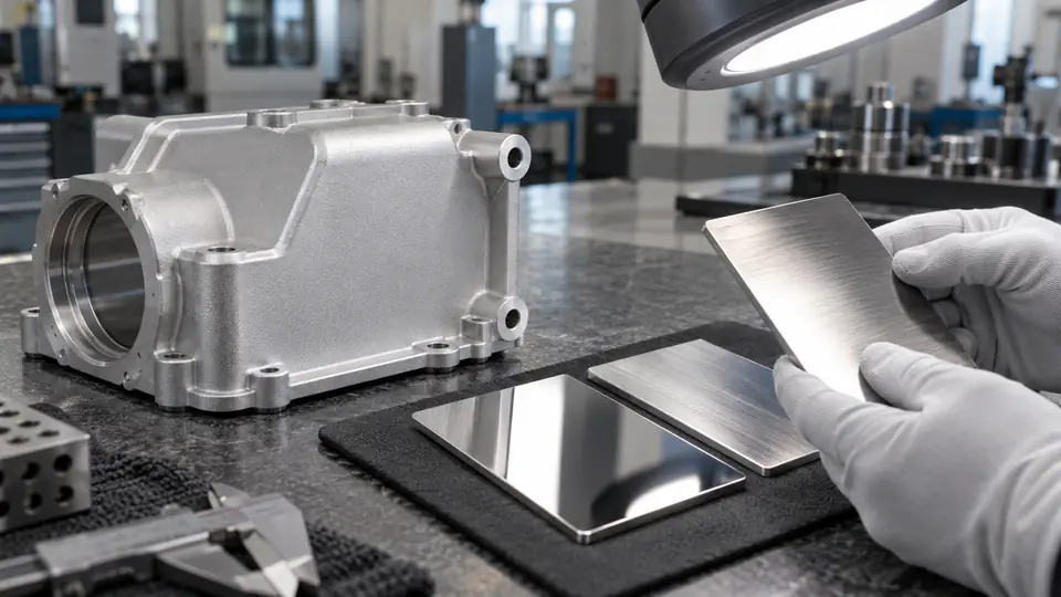
“Good finish,” “no scratches,” and a global Ra value do not produce a quote-ready CNC surface requirement. They mix three different decisions: microscopic texture needed for function, visible appearance accepted by people, and a coating or treatment that changes the final surface. A supplier may interpret the same note as a standard machined face, a polished cosmetic panel, or a fully reworked show surface—and price each very differently.
This surface finish callout CNC drawing guide shows how to separate functional texture from visual quality, define zones and viewing conditions, select controlled samples, account for finishing processes, and create a reproducible inspection plan. It is written for buyers preparing an RFQ, not as a replacement for ASME B46.1, ISO 21920, a coating standard, or a product-specific cosmetic specification.
Separate Surface Texture, Appearance, and Treatment
Surface texture describes geometric irregularities. It includes roughness, waviness, and lay, and standards such as ASME B46.1 and the ISO 21920 series define parameters and specification practices. Appearance is a visual judgment involving scratches, tool marks, dents, stains, color, gloss, and uniformity. Treatment is the process applied after machining, such as anodizing, plating, passivation, polishing, bead blasting, painting, or conversion coating.
These conditions interact but are not equivalent. A surface can meet Ra and still show an objectionable directional tool mark. Two anodized surfaces can have similar roughness but visibly different color because of alloy, temper, pretreatment, coating thickness, dye, seal, and viewing light. A polished face can look uniform while failing a sealing requirement because waviness remains.
Use separate callouts for each decision:
- a texture specification for the functional surface;
- a cosmetic-zone specification for visual acceptance;
- a process callout for coating or treatment;
- a dimensional state identifying whether acceptance is before or after finishing.
Start with the Function of Each Surface
Review the part face by face. Ask whether each surface seals, slides, bears, locates, transfers heat, bonds, reflects light, contacts a user, remains hidden, or only clears another component. The answer determines which parameter and inspection method are useful.
A gasket land may need roughness, lay, flatness, and defect controls. A bearing seat may need diameter, roundness, texture, and lead controls. A thermal interface may need flatness, waviness, cleanliness, and a defined contact material. A painted exterior housing may be governed mainly by visible defects and color. A hidden pocket may need only removal of loose burrs.
Avoid specifying the same fine finish on every machined surface. It can require smaller stepovers, additional passes, polishing, special handling, and full visual inspection while providing no functional benefit in hidden or noncontact areas.
Define Cosmetic Zones on the Drawing
Cosmetic importance is rarely uniform. Use a zone map or face identifiers to classify surfaces by visibility and consequence. A simple system might define:
| Zone | Typical location | Acceptance approach |
|---|---|---|
| A | Primary user-facing or optical exterior | Controlled visual standard, strict defect limits, color/gloss comparison |
| B | Visible during normal assembly or use | Moderate cosmetic limits with defined viewing conditions |
| C | Normally hidden but exposed during service | Workmanship limits; no loose burrs, corrosion, or handling damage |
| D | Internal or nonvisible process surfaces | Functional drawing requirements only |
The letters have no universal meaning. Define them in the project specification and show each zone unambiguously on the model or drawing. If an edge separates A and C zones, state which side owns the transition.
Zone maps prevent the polishing team from treating a hidden pocket like a front panel and prevent handling marks on a critical visible face from being dismissed as “within roughness.”
Specify Viewing Conditions
Visual acceptance changes with lighting, distance, angle, time, and magnification. Without a controlled viewing method, two inspectors can reach different conclusions from the same part.
A cosmetic specification should state:
- light source type or color temperature and approximate illumination;
- viewing distance and angle range;
- observation time;
- whether unaided vision or specified correction/magnification is used;
- part orientation and whether the surface is rotated;
- background color and glare control where important;
- cleaning condition before inspection.
The method should represent normal product use. A handheld enclosure inspected at close distance needs a different method from an interior machine plate. Do not use extreme grazing light unless that condition is part of the requirement; it can reveal harmless marks that are invisible in service.
Define Defects with Size and Location Limits
Terms such as scratch, dent, pit, stain, streak, chatter, burn, cloudiness, and discoloration need project definitions. Where the distinction matters, include diagrams or reference photographs.
State whether each defect is prohibited, allowed up to a size/count, or controlled by an approved boundary sample. Include spacing or accumulation rules. For example, allowing three small marks may still be unacceptable if they cluster in a logo area.
Do not invent a numerical scratch limit that no one can measure consistently. Fine marks may be better judged against a physical sample or a calibrated visual comparator. Larger dents or pits may be measured dimensionally. Choose a method whose repeatability is appropriate to the acceptance margin.
Use Boundary Samples Correctly
A boundary sample represents the limit of acceptable appearance, not the ideal part. Create it from the same material, alloy condition, machining texture, pretreatment, coating, color, and geometry as production where possible. Curved and flat surfaces can reflect differently, so a flat coupon may not represent a complex housing.
Identify every approved sample with:
- sample ID and revision;
- part or coupon definition;
- material and process route;
- date and approving authorities;
- zones or defects represented;
- lighting and viewing conditions;
- storage, cleaning, handling, and replacement rules.
Keep a matched sample or controlled high-quality record with both buyer and supplier. Photographs are useful for communication but should not be the sole color authority unless the imaging and display workflow is calibrated.
Specify Ra Only When It Relates to Function
Ra is the arithmetic mean roughness over the evaluated profile. It compresses a complex surface into one value. Different peak shapes, valley depths, spacing, and lay can produce similar Ra. NIST surface-roughness calibration work identifies multiple parameters, including Ra, Rq, Rz, Rt, Rp, Rv, and RSm, because no single number describes every function.
Select a parameter based on the surface’s job. Rz or maximum-height parameters may reveal peaks and valleys that Ra averages. Material-ratio parameters can help describe plateaued sliding or sealing surfaces. Waviness may matter on optical, sealing, or thermal faces. Lay direction can affect leakage, friction, wear, and appearance.
The drawing should identify the governing standard and edition, parameter, limit, filtering or cutoff conditions where needed, evaluation length, lay, and surface zone. If defaults in the selected standard apply, ensure the supplier and buyer use the same edition.
Account for Measurement Direction and Location
A stylus result depends on where and in which direction the trace is taken. Measuring parallel to milling lay can produce a different result from measuring across it. Small lands, bores, curved faces, interruptions, and soft coatings can limit instrument access.
Mark the evaluation direction where lay is directional. Define the number and location of traces for a large or variable surface. Avoid requiring a contact stylus on a delicate coating unless the method is suitable.
For areal measurements or optical methods, specify the method, measured area, filters, data processing, and treatment of missing points. A supplier’s color topography image is not an acceptance result unless it uses the agreed calculation and limits.
Distinguish Roughness from Waviness and Form
Roughness captures shorter-wavelength surface features after filtering. Waviness covers longer spatial features, while form includes overall shape. A face can have low Ra yet be bowed; a polished sealing land can be smooth but wavy.
ASME surface-texture guidance illustrates filtering used to separate these wavelength bands. Apply flatness, profile, or waviness controls as required rather than expecting Ra to control them.
For a gasket face, for example, evaluate:
- flatness or profile across the sealing zone;
- local waviness relative to gasket compliance;
- roughness and lay at the contact;
- scratches or dents crossing the seal path;
- coating or plating condition;
- cleanliness at assembly.
The functional limit should come from the seal design and validation.
Communicate Machined Appearance
Visible tool marks are not automatically defects. A face-milled pattern may be intentional, while chatter, witness steps, tool pullout, or hand blending may be unacceptable. State whether a uniform as-machined pattern is allowed and which transitions must be visually continuous.
If several faces must match, say whether the requirement applies within one part, across an assembled set, or between production lots. Toolpath direction, stepover, tool condition, and fixture orientation affect appearance. Requiring matched lay across separate parts can add setup and sorting cost.
Do not request “mirror finish” without a measurable or visual definition. The term can imply anything from a fine machined surface to multi-stage polishing. Specify the final function, texture or gloss parameter, visual comparator, and permitted edge rounding.
Control Bead Blasting and Brushing
Bead blasting can create a matte appearance and reduce the visibility of machining marks. Media material, size, condition, pressure, distance, angle, duration, and equipment cleanliness influence texture and color after anodizing. Used media can embed contamination or produce inconsistent surfaces.
Define which zones are blasted, which are masked, and what transition is acceptable. Blast before coating unless a qualified specification says otherwise. Establish whether holes, threads, bearing seats, sealing lands, and marking are protected.
Brushing creates directional lay. Specify direction relative to the part, acceptable overlap, treatment around holes and radii, and boundary-sample appearance. Hand brushing of complex geometry can vary substantially between operators; qualify the route before high-volume release.
Account for Anodizing
Anodized appearance depends on alloy, temper, stock history, surface preparation, coating type and thickness, dye, sealing, racking, geometry, and lot. Welds, cast regions, inserts, and different aluminum alloys may not color match.
State coating type, class or color, governing specification, thickness when required, sealing, masking, rack-mark zones, and cosmetic acceptance. Identify whether the color must match a physical standard and the permitted range of gloss or color difference.
Coating changes dimension and can reveal or obscure substrate texture. Inspect critical fits and cosmetic condition in the final state. If pre-anodize roughness is controlled to achieve final appearance, define both checkpoints only where necessary.
Specify Plating, Passivation, and Paint by Function
Electroless nickel, electroplating, passivation, conversion coating, and paint each have distinct purposes and dimensional effects. Identify specification, type or class, thickness, heat treatment, color, adhesion, masking, and test requirements as applicable.
Plating can build differently at edges, recesses, and holes. Paint may bridge small features, create orange peel, or accumulate at corners. Passivation normally does not create a thick decorative layer and should not be used as a vague appearance instruction.
If appearance is critical after a finish, create final-state acceptance criteria. A raw-machined sample cannot authorize a coated visual result.
Protect Critical Faces During Manufacturing
Cosmetic damage often occurs after machining: during deburring, inspection, washing, outside processing, assembly, or packaging. The route should identify when a surface becomes cosmetically complete and how it is protected afterward.
Use clean, nonabrasive supports and separators. Keep metal chips away from finished faces. Avoid adhesive films that leave residue or react with coatings. Handle parts with appropriate gloves where fingerprints or corrosion are risks.
Protection must not hide defects during final inspection. Define whether film is applied before or after inspection and how the customer should remove it.
Treat Edge Breaks as Designed Features
Edges influence both safety and appearance. A vague “deburr” note may produce inconsistent chamfers, rolled edges, or hand-polished transitions. Critical visible edges need a controlled break or radius and a visual standard for blend.
On anodized parts, sharp edges can receive thinner or visually different coating. Large hand breaks can expose facet variation. On sealing surfaces, an edge break can reduce the usable land. Identify allowable edge condition by zone and prevent burr-removal methods from changing adjacent geometry.
For intersecting holes and internal passages, specify freedom from loose burrs separately from cosmetic requirements.
Build a Practical Inspection Plan
Use different tools for different decisions:
| Requirement | Appropriate evidence | Inadequate substitute |
|---|---|---|
| Profile roughness | Calibrated profilometer result using specified settings | Fingernail or visual judgment |
| Waviness or form | Suitable profile/areal method or dimensional metrology | Ra alone |
| Color | Controlled sample or defined color measurement method | Uncalibrated email photo |
| Gloss | Glossmeter with defined geometry and method | “Looks shiny” |
| Scratch/dent limits | Controlled visual method, comparator, or dimensional measurement | “Workmanship acceptable” |
| Coating thickness | Qualified coating-thickness method and sampling | Process certificate alone |
| Cosmetic-zone acceptance | Inspection under defined lighting, distance, time, and boundary sample | Inspection at any available bench |
Agree on sampling. A user-facing surface may require 100% visual inspection while a stable roughness process uses sampling. Define lot, sample selection, escalation, and disposition rules.
Correlate Buyer and Supplier Inspection
Disputes often arise because both parties follow different methods. Before production, compare instruments, calibration, filters, trace direction, surface cleaning, lighting, sample condition, and acceptance rule.
Measure the same pilot parts or check specimens at both locations. If results differ materially, identify the measurement cause before changing the machining process. For visual acceptance, conduct a joint boundary-sample review with representatives from design, quality, procurement, supplier machining, and finishing.
Record the agreed interpretation in the purchase package. A meeting photo without sample identity, method, and approval does not create durable correlation.
Price the Requirement Transparently
Surface requirements can affect tool selection, stepover, speed, finishing passes, polishing, masking, outside processing, handling, inspection, rejects, and packaging. Ask the supplier to separate:
- standard machining included in the base price;
- special toolpath or polishing time;
- coupons and sample approval;
- coating or outside finish;
- masking and rack-control work;
- full or sampled cosmetic inspection;
- texture, gloss, color, or coating measurement;
- special protection and packaging.
This breakdown helps engineering improve value. Relaxing a hidden pocket may save time; relaxing a critical seal land may create field risk. Make changes by zone and function rather than applying a blanket finish reduction.
Qualify a Finish Before Production
Use a staged approval when appearance carries commercial risk. Begin with a machined coupon or representative part to confirm toolpath, texture, and edge treatment. Apply the production-intent pretreatment and coating to parts from the specified alloy and stock condition. Review the results using the final viewing and measurement methods, then approve the boundary rather than an unusually perfect show sample.
Record process variables that materially affect the result, but do not force the supplier to disclose unrelated proprietary settings. The controlled record might identify material lot, machine route, abrasive or blast media family, coating specification, approved processor, masking drawing, rack location, sample identity, and inspection results. If a buyer mandates a processor or exact route, the purchase documentation should state that constraint.
Production validation should include variation within a lot and, when risk warrants it, across more than one lot. Color and gloss consistency cannot be inferred from a single part. Compare mating components together if the final product requires a visual match. Define whether replacement parts must match the current assembly, the original master, or only the current specification range.
Changes in alloy source, temper, pretreatment, media, coating line, dye, seal, polishing method, or repair practice may require renewed approval. The change plan should name who evaluates impact and whether dimensional, corrosion, adhesion, or cosmetic tests are repeated.
Write a Quote-Ready Callout
A complete surface section might include:
- Governing standards: the applicable surface-texture and finish specifications with editions.
- Zone map: faces identified as A, B, C, or functional-only zones.
- Texture controls: parameter, limit, lay, location, measurement settings, and final state.
- Cosmetic criteria: defect definitions, size/count rules, viewing conditions, and samples.
- Treatment: exact process, class, thickness, color, sealing, masking, and rack marks.
- Protection: handling, cleaning, film, separators, and packaging.
- Evidence: inspection report, coating certificate, sample approval, and lot traceability.
Use a drawing detail to show boundaries that cannot be described safely in a note.
Common Callout Failures
“All surfaces Ra 0.8 µm”
This may overcontrol hidden faces and still fail to define waviness, lay, scratches, color, or coating. Apply texture only to functional zones and specify other concerns separately.
“No scratches”
At enough magnification every manufactured surface has irregularities. Define defect size, count, zone, and viewing method or use a controlled boundary sample.
“Black anodize, match sample”
Identify the sample, alloy, coating specification, color range, gloss, pretreatment, rack zones, and final inspection method. Check whether the sample is stable and representative.
A photograph is used as the color master
Camera, light, compression, display, and white balance alter color. Use photography for communication and traceability, not as an uncontrolled substitute for the approved standard.
The supplier polishes through a dimensional limit
Identify which dimensions apply after polishing and coating. Control stock removal, edge rounding, and final inspection at the same process state as acceptance.
RFQ Checklist
Before sending the quote package, verify that:
- each surface requirement is tied to function or visible use;
- texture, cosmetic appearance, and treatment are separate;
- cosmetic zones and boundaries are shown;
- viewing conditions and defect rules are defined;
- physical samples have IDs, revisions, approvals, and storage controls;
- texture parameters include method details and lay where needed;
- flatness, waviness, and roughness are not treated as interchangeable;
- coating type, thickness, color, sealing, masking, and rack marks are explicit;
- edge breaks protect both appearance and functional geometry;
- final-state measurement and sampling are agreed;
- handling and packaging preserve the accepted surface;
- suppliers must state assumptions and exceptions in the quote.
Make Appearance Reproducible
A strong surface callout lets an engineer, machinist, finisher, inspector, and buyer reach the same acceptance decision. It controls the surface features that matter, leaves noncritical zones economical, and measures the part in the state in which it will be used.
That shared decision is the deliverable.
Send the 3D model and controlled 2D drawing with the zone map, finish specification, boundary samples, quantities, and inspection needs. QuickCNCs can review machining strategy, surface generation, finishing handoffs, and measurement through CNC milling services and surface grinding services. When the requirement is ready, submit it through Request a Quote.
References
- ASME B46.1: Surface Texture — terminology and specification parameters for roughness, waviness, and lay.
- ISO 21920-2:2021 — terms, definitions, and parameters for profile surface texture.
- NIST surface roughness and step-height calibrations — measurement conditions and roughness parameters.