
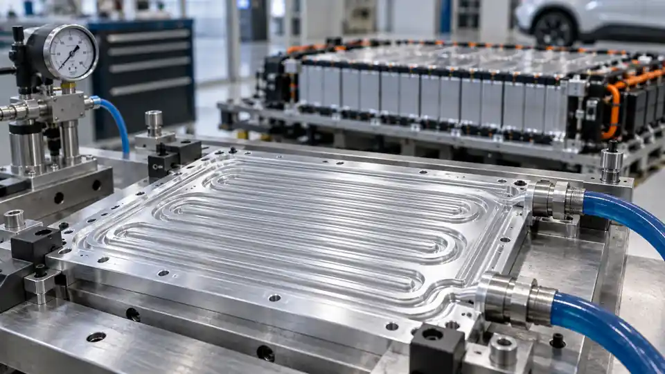
An EV battery-module cooling plate is simultaneously a heat exchanger, a pressure boundary, a structural interface, and a production assembly. Choosing CNC machining because the channels are complex—or rejecting it because material removal looks expensive—misses the real decision. The manufacturing route must deliver coolant distribution, low pressure drop, leak integrity, flat thermal contact, corrosion compatibility, and repeatable joining at the required volume.
This EV battery cooling plate CNC machining decision guide explains how to move from thermal requirements to a quote-ready part and when machining is suitable for prototypes, validation, bridge production, or series manufacture. Values such as allowable pressure drop, proof pressure, flatness, temperature, and leak rate must be supplied by the battery-system owner. The examples describe an engineering method, not universal limits.
Begin with the Thermal-System Requirement
The plate geometry should come from a thermal model and test plan. Battery cells generate heat during charging and discharging, and temperature affects performance, life, and safety. Department of Energy and NREL resources describe thermal management as a critical part of electric-drive systems and discuss liquid cooling as a common approach. The cooling plate must be evaluated within that complete system: cells or modules, interface material, coolant, pump, valves, heat exchanger, controls, and vehicle environment.
Define the following inputs before asking a supplier to optimize a channel:
- heat generation by location and operating mode;
- acceptable cell or module temperature range;
- maximum temperature difference across the module;
- coolant type, concentration, inlet temperature, and property range;
- target flow, available pressure drop, and pump behavior;
- ambient and cold-start conditions;
- transient events, fast charging, and fault cases;
- thermal-interface material and compression;
- plate orientation, module load, and mounting constraints.
A supplier can help make a channel machinable, but it cannot infer the correct thermal boundary from a CAD file alone.
Decide Whether CNC Machining Fits the Program Stage
CNC machining is attractive for prototype and validation plates because channel depth, width, routing, port position, wall thickness, and mounting features can change without hard tooling. It provides a controlled way to test competing thermal concepts using production-intent alloys and interfaces.
Machining may also suit low-volume or specialized packs where integration, high mix, or qualification cost outweighs raw material removal. A machined base joined to a cover can consolidate mounting bosses, seals, manifolds, sensor pockets, and complex local flow features.
At high automotive volume, stamped, roll-bonded, extruded, brazed, cast, or otherwise near-net routes may deliver lower unit cost and better material yield. They introduce their own tooling, minimum volume, geometry, joining, cleaning, and validation constraints. Machining can remain valuable for datums, sealing surfaces, ports, and critical interfaces on a near-net blank.
| Program condition | Machined plate is often useful | Route question before commitment |
|---|---|---|
| Concept prototype | Channel and port designs are changing | Can the joined prototype represent production thermal behavior? |
| DVT or validation | Material and interfaces are becoming controlled | Which process differences require repeated durability tests? |
| Bridge production | Tooling is not ready or volume is limited | Can machining capability and join yield meet the interim demand? |
| Series production | Low volume, high integration, or premium application | Does a near-net route reduce total cost without losing qualification? |
Compare routes on validated performance, tooling, change cost, material yield, joining yield, inspection, leak testing, corrosion, cleanliness, and capacity—not on machining hours alone.
Select the Plate Architecture
Common architectures include a machined channel plate closed by a sheet or second machined part, an extruded multiport section with machined manifolds, a stamped pair joined around formed channels, or a cast body with machined sealing and mounting features. Each architecture distributes risk differently.
A machined-base-and-cover design gives direct access to channels before joining. It can support varying depths, local turbulators, complex manifolds, and integrated ports. The closing method must seal every channel without unacceptable distortion or blocked flow.
An extruded section can reduce material removal and provide repeated straight channels. Cross-flow routing, turns, and manifolds then need end features or separate components. A stamped or roll-bonded plate may be light and fast at volume but requires dedicated tooling and careful control of formed height and joining. A casting can integrate three-dimensional features, yet porosity, cleanliness, and leak integrity must be qualified.
Freeze the architecture only after thermal, structural, manufacturing, joining, and service teams have reviewed the same boundary conditions.
Design Channels for Flow Distribution
Equal nominal channel dimensions do not guarantee equal flow. Header shape, inlet position, outlet position, channel length, turns, local restriction, surface condition, and air trapping all affect distribution. A channel near the inlet can take excessive flow while a remote region runs hot.
Use computational analysis and representative tests to evaluate total pressure drop and branch balance. Include coolant property variation with temperature and concentration. Identify whether flow can reverse, whether the system must self-vent, and how trapped gas is removed.
Machinability matters. Narrow deep channels require small or long tools, increase cycle time, complicate chip evacuation, and create fragile ribs. Sharp internal corners are produced with a radius unless another process is used. A thermal design that assumes knife-edge fins or zero-radius turns may not be practical to mill.
Ask the supplier to mark tool diameter, reach, minimum remaining wall, corner radii, and inaccessible features on the design. Then rerun the thermal model with the manufacturable geometry before release.
Control Rib and Wall Geometry
Ribs separate channels, support the cover, and conduct heat. Too little width can cause tool deflection, collapse during joining, or local leak paths. Excessive width reduces flow area and can create a thermal bottleneck. The optimum is an engineering balance, not the smallest feature a catalog says a machine can cut.
Minimum floor thickness should account for pressure, external module load, impact or vibration, corrosion allowance where applicable, flatness, and machining variation. The local floor below a deep channel may behave differently from the thick external frame. Include port and fastener loads, not only internal coolant pressure.
Avoid abrupt thickness transitions when possible. They concentrate stress and respond differently to cutting, heat, clamping, and joining. Smooth transitions can improve both structural performance and dimensional stability.
Dimension critical ribs and floors from functional datums. A general profile tolerance may control the envelope, but the pressure boundary may need explicit minimum material requirements that cannot be verified from external dimensions alone.
Establish a Functional Datum System
The cooling plate usually interfaces with modules or cells, a pack frame, coolant connections, seals, and sometimes electrical isolation components. The datum system should represent how those interfaces constrain the part.
A primary thermal-contact plane may establish the module interface, mounting holes or dowels can locate the plate in the pack, and a port or clocking feature may control orientation. Another design may use the structural mounting plane as primary. The order should follow assembly function.
State which condition is inspected: free, bolted to a simulated frame, assembled with interface material, or after pressure. If the plate is measured while clamped, define the fixture, support locations, fastener sequence, and torque. An arbitrary inspection fixture can hide bow that returns in the pack.
Relate channel position and minimum walls to the external datum frame. This helps avoid drilling a mounting hole or sensor pocket into a channel after a revision.
Plan Flatness and Thermal Contact
Heat transfer across a module-to-plate interface depends on contact area, interface material, pressure, surface shape, texture, and contamination. A single flatness number does not describe the full interface, but it is an important component.
Define the functional zone rather than applying a costly limit to the entire casting or flange. If discrete modules contact separate pads, profile or coplanarity of those pads may be the controlling characteristic. Include local waviness if the interface material cannot bridge it.
The plate can change shape during channel machining, cover joining, heat treatment, pressure testing, and assembly. Set intermediate checkpoints only where they help control the final result. The final acceptance state must be explicit.
Do not rely on manual flattening as an undocumented production step. If a straightening operation is allowed, qualify its effect on fatigue, channel integrity, finish, and repeatability.
Select Alloy, Temper, and Stock Form
Aluminum is common because of its thermal conductivity, density, machinability, and availability. Alloy and temper selection must also consider strength, corrosion with the selected coolant, joining process, formability, stock thickness, supplier availability, and exposure temperature.
Wrought plate may offer a predictable starting structure for machining. Extrusion enables continuous channels but creates directional properties and section constraints. Brazing-sheet alloys and clad products are selected as part of a brazing system; substituting a similar-looking alloy can change joint formation and corrosion behavior. Cast material requires porosity and cleanliness control suitable for a pressure boundary.
State alloy, temper, product form, specification, and permitted alternatives. Require approval before any change in source or material condition where it could affect joining, corrosion, strength, or thermal performance.
Material certificates establish identity; they do not alone prove leak-tightness, dimensional stability, or coolant compatibility.
Compare Joining Methods
A machined channel needs a cover or mating component. Options can include vacuum brazing, controlled-atmosphere brazing, friction-stir welding, laser welding, adhesive bonding, diffusion bonding, gasketed fastening, or another qualified method. Each creates different heat input, distortion, metallurgy, cleanliness, serviceability, and inspection needs.
Brazing can join broad internal networks but requires compatible alloys, joint clearance, cleanliness, filler control, and a furnace cycle. Thermal exposure can change temper and shape. Welded routes localize or move heat differently and need start-stop, penetration, and crack controls. Adhesives limit temperature and chemistry and may introduce outgassing or long-term durability questions. A bolted gasketed cover can be serviceable but adds mass, fasteners, seal compression, and potential bypass paths.
Do not leave “join cover” as a supplier assumption. Define joint type, material set, pressure and leak requirements, allowable distortion, cleanliness, corrosion validation, and whether repair is permitted. The supplier should propose the detailed process and qualification evidence.
Design Ports and Seals as Interfaces
Ports transfer structural and plumbing loads into the plate. Specify tube or fitting standard, thread, sealing concept, insertion depth, orientation, wrench access, and allowable load. A port that fits in open space may be impossible to assemble once modules and pack walls are present.
For O-ring seals, define gland geometry through the applicable seal design requirements, material compatibility, surface finish, edge condition, and compression state. Avoid intersecting the groove with porosity, weld starts, or uncontrolled machining marks. If a face seal is used, control the full sealing land after joining.
Pressure taps, temperature sensors, drain points, and vents should be located in the hydraulic model and service plan. Blind cavities can trap air during fill or test fluid after cleaning.
Manage Machining Distortion
Removing a large fraction of plate stock releases residual stress and creates an unbalanced section. Thin floors can move under cutting force and recover afterward. Workholding can temporarily flatten a plate, causing the machine to cut a geometry that does not exist in the free state.
A robust route may use suitable stress-relieved stock, balanced roughing, controlled stock allowance, low-stress support, intermediate stabilization, and finish machining from functional datums. The supplier should propose the route based on equipment and part geometry.
The design team can help by avoiding isolated thin regions, providing clamping lands, allowing reasonable internal radii, and distinguishing functional flat zones from noncritical areas. If the cover-joining cycle dominates final shape, machining limits before joining should support that downstream transformation rather than pretend it does not occur.
Deburr and Clean Internal Passages
Loose chips or burrs can obstruct channels, damage pumps, contaminate coolant, or migrate into a valve. Intersecting drillings, small turns, threaded ports, and deep milled channels need an explicit internal-edge and cleanliness plan.
Use visual or borescope inspection where access permits. Flow, pressure-drop, or mass-based flushing checks can supplement visual inspection. The cleaning chemistry must be compatible with alloy, braze, weld, seal, and final coolant. Define rinse quality, drying, preservation, and capped shipment.
Do not specify “free of debris” without a verification method. The test could define maximum retained particle size and mass, extraction procedure, filter, inspection equipment, acceptance, and record. Requirements should be proportional to the downstream system and agreed before quotation.
Verify Dimensions at the Correct Process Stage
Mark characteristics as pre-join, post-join, or final assembly. Channel width and depth may be accessible only before the cover is attached; final flatness, port orientation, and seal faces must be verified after joining. Minimum wall may require coordinate data, ultrasonic inspection, CT for selected development parts, or controlled process evidence depending on accessibility and risk.
Inspection reports should include actual values and the datum setup. A final pass statement cannot show drift in flatness, port position, or channel depth. If the part is measured at a controlled temperature, state it.
Where the joining process shifts a critical feature, define whether the supplier machines that feature afterward, controls it through a qualified offset, or accepts it in a mounted condition. Avoid undocumented selective assembly.
Build a Pressure and Leak-Test Specification
Proof, burst, and leak tests answer different questions. A proof test demonstrates survival at a defined pressure and duration without unacceptable permanent change or leakage. A burst test characterizes ultimate behavior and is normally destructive. A leak test finds flow across the pressure boundary using a defined medium and sensitivity.
The drawing or test specification should state:
- test medium and its cleanliness and compatibility;
- test pressure, ramp, dwell, temperature, and sequence;
- which ports are connected or sealed;
- external restraint and fixture condition;
- allowable pressure decay or measured leak rate;
- instrument range, resolution, calibration, and background correction;
- post-test drying and preservation;
- sampling frequency and record requirements.
Air-under-water, pressure decay, mass flow, tracer gas, and liquid methods have different sensitivities and interpretation. Select the method from the allowable real leak and safety requirements. Never use high-pressure gas casually; the fixture and procedure require a formal safety review.
Test Flow and Pressure Drop
A leak-tight plate can still distribute coolant poorly. Flow testing should reproduce the specified fluid properties or use a correlated surrogate. State inlet and outlet conditions, flow range, temperature, measurement accuracy, and stabilization time.
Measure total pressure drop and, where necessary, branch balance. Development plates may need detailed mapping to validate the model. Production tests can often use a simpler correlated check after the process is qualified.
Keep the test circuit clean and control trapped air. Record the plate orientation and fill procedure. A comparison made with different air content or temperature can create a false process signal.
Validate Thermal Performance
Thermal validation needs representative heat input, contact materials, compression, coolant, flow, ambient conditions, and sensor placement. Compare maximum temperature, temperature spread, transient response, and pumping demand with the system limits.
The test should distinguish cooling-plate performance from variation in heaters, cells, interface pads, fixture force, and sensors. Calibration and uncertainty matter when a design decision depends on a small temperature difference.
Use development results to update the model and manufacturing controls. If a channel change improves pressure drop but creates a hot region, the route is not ready. If a process change alters surface flatness or joining thickness, repeat the tests affected by those interfaces.
Plan Corrosion and Coolant Compatibility
Coolant chemistry, temperature, dissolved oxygen, contaminants, mixed metals, electrical potential, and time influence corrosion. The cooling plate must be evaluated as part of the full loop, including fittings, pumps, radiators, inhibitors, and seals.
Avoid assuming that aluminum alloy identification alone proves compatibility. Joined regions, clad layers, heat-affected zones, machined bare surfaces, and trapped crevices may behave differently. Specify coolant composition and maintenance limits, then use application-appropriate corrosion and aging tests.
If external surfaces receive coating, define masking around thermal contacts, electrical bonds, ports, and seals. Any internal coating needs separate review for coverage, adhesion, thermal resistance, particle release, and repair.
Integrate Structural and Durability Requirements
The plate may support modules, react clamp loads, attach to the pack, or contribute to crash structure. Internal pressure combines with bolt loads, gravity, road vibration, impact, and thermal cycling. Analyze the correct boundary conditions and include joint degradation.
Durability tests may include pressure cycling, thermal cycling, vibration, mechanical shock, coolant aging, and combined environmental exposure. Sequence matters: a plate can pass a new-part leak test and leak after vibration or thermal fatigue.
Track deformation as well as leakage. Permanent bow can reduce thermal contact even if the pressure boundary remains intact.
Prepare a Quote-Ready RFQ
Supply a package that includes:
- a neutral 3D model and controlled 2D drawing with revision authority;
- channel, port, seal, mounting, and thermal-contact definitions;
- material, temper, stock form, joining, coating, and substitution rules;
- coolant, flow, pressure, temperature, and environmental conditions;
- free-state and mounted-state dimensional requirements;
- prototype, validation, bridge, and series quantities;
- pressure, leak, flow, cleanliness, and thermal test specifications;
- inspection records, material records, and traceability needs;
- packaging, caps, dryness, and preservation requirements;
- expected design-freeze and validation milestones.
Ask each bidder to identify manufacturing assumptions, outside processes, tooling, sample size, destructive tests, capacity, repair policy, and exclusions. Compare quotations against the same test boundary.
Common Failure Modes
The plate passes leak test but has poor cooling uniformity
Check branch flow, trapped air, channel restriction, interface pressure, sensor placement, and real heat input. Add correlated flow and thermal checks rather than tightening an unrelated dimensional tolerance.
Final flatness fails after brazing or welding
Review material condition, section balance, joint clearance, thermal cycle, fixture, cooling, and measurement state. Agree on a controlled compensation or post-join machining plan and repeat durability tests affected by the change.
Debris appears in the coolant loop
Trace chips, burrs, abrasive, braze residue, corrosion products, plug materials, and packaging. Contain the lot, inspect internal passages, and correct both the source and cleaning verification.
Ports leak after vehicle vibration
Evaluate fitting support, installation torque, thread or weld quality, local wall stiffness, tube loads, seal condition, and test sequence. Static leak acceptance may not represent the combined environment.
A production route does not match prototype performance
List every difference in alloy, channel geometry, surface, joining, flatness, interface material, and test setup. Revalidate the affected requirements; do not treat the production plate as equivalent because its outer envelope matches.
Final Decision Checklist
Before approving a cooling-plate route, verify that:
- system thermal loads and coolant limits are defined;
- channel geometry is both modeled and manufacturable;
- minimum ribs and walls survive pressure, joining, and assembly;
- functional datums reflect module and pack interfaces;
- flatness is specified in the correct final state;
- alloy, temper, stock form, and joining process are compatible;
- ports, seals, vents, and drains are serviceable;
- internal passages have a deburr and cleanliness verification plan;
- dimensional inspection covers pre-join and post-join needs;
- leak, flow, and pressure tests use defined methods and records;
- thermal, corrosion, vibration, and cycling validation match the application;
- the volume route has a controlled transition from prototype evidence.
Choose the Route by Verified System Performance
CNC machining is often the fastest way to learn which cooling-plate design works, and it can remain the correct production process for low-volume or highly integrated hardware. Its value comes from flexible geometry and precise interfaces. The buyer still needs to close the joining, flatness, flow, leak, cleanliness, corrosion, and durability requirements.
Send the 3D model and controlled 2D drawing together with coolant conditions, thermal limits, pressure and leak tests, joining concept, quantities, and program stage. QuickCNCs can review channel machinability, workholding, datums, port features, inspection, and bridge-production options through CNC milling services and rapid prototyping. Use Request a Quote when the technical baseline is ready.
References
- U.S. Department of Energy: Advanced battery development, system analysis, and testing — battery-system integration and validation context.
- NREL battery thermal management — cooling-strategy and thermal-model context.
- Argonne National Laboratory BatPaC — battery-pack design model with liquid-cooling system discussion.