
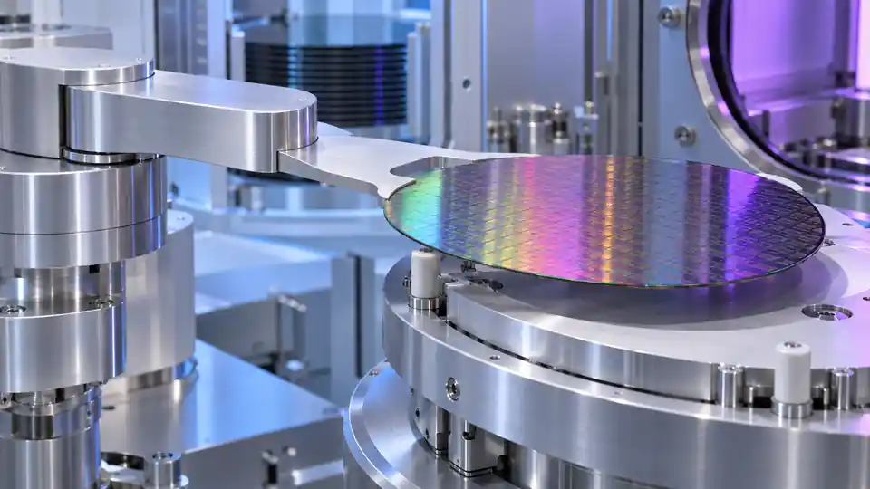
Wafer-handling hardware places precision mechanics directly beside a fragile, contamination-sensitive product. A robot blade, aligner chuck, edge gripper, nest, lift-pin plate, or vacuum end effector can meet its drawing dimensions and still fail in service if it sheds particles, traps process residue, distorts the wafer, obscures sensors, or locates from the wrong physical reference.
This wafer handling CNC hardware decision guide focuses on the information a semiconductor-equipment buyer should define before requesting a machining quote. It covers coordinate systems, contact strategy, flatness, vacuum distribution, material and finish selection, cleaning, inspection, packaging, and functional qualification. Exact cleanliness classes, materials, limits, and test methods must come from the tool owner and applicable SEMI standards; they should not be inferred from a general machining article.
Define the Hardware’s Function and Environment First
“Wafer handling” describes many different conditions. A part may operate in a load port, atmospheric robot, pre-aligner, vacuum transfer module, process chamber, metrology station, or shipping environment. Pressure, temperature, chemistry, particle sensitivity, electrostatic controls, allowable outgassing, and access for maintenance vary greatly among those locations.
Start the RFQ with a short use description:
- wafer diameter, thickness range, notch or flat, and any warped-wafer condition;
- atmospheric, inert, or vacuum environment and the pressure range;
- maximum and minimum operating and bake temperatures;
- process gases, vapors, cleaners, and incidental chemical exposure;
- acceleration, speed, orientation, and emergency-stop load;
- allowed wafer-contact zones and prohibited exclusion zones;
- cleanliness, ionic, metallic, and organic contamination requirements;
- grounding, static-dissipation, or electrical-isolation needs;
- expected cycles, service interval, and replacement method.
Without this context a supplier can only quote geometry. The technically correct material and cleaning route for an atmospheric cassette component may be unsuitable inside a vacuum process chamber.
Establish the Wafer Coordinate System
Location data must refer to a common physical coordinate system. SEMI M20 addresses a wafer coordinate system using wafer center as the origin and Cartesian or polar coordinates for locations on the surface. A drawing does not have to reproduce that standard, but it should state how the equipment coordinate frame relates to wafer center, surface, and notch or flat.
Define what locates the wafer during each operation. Possibilities include edge contacts, three-point support, a vacuum land, a center feature used only during alignment, or a kinematic set of stops. The reference used by the mechanism, vision system, and inspection method must agree. If the CMM reports a blade from convenient external edges while the robot calibrates from the pickup pads, the inspection report may not predict handoff accuracy.
For an end effector, identify:
- the mounting interface to the robot wrist;
- the frame used to calibrate wafer center;
- the height or plane of the wafer support points;
- the angular reference for notch or feature orientation;
- the allowable error at the actual wafer position, not only at the mounting flange.
A long, thin blade magnifies small angular errors. Apply the system error budget at the wafer center or edge location that matters to the transfer.
Select a Contact Strategy
Contact should be intentional, limited, and inspectable. Backside contact may be permitted in some processes and prohibited in others. Edge handling can reduce backside contact but introduces local stress and sensitivity to diameter, edge profile, and gripper force. Vacuum pickup distributes restraint differently and adds holes, grooves, seals, and a fluid path that must remain clean.
| Contact method | Advantages | Risks to control |
|---|---|---|
| Three-point backside support | Determinate support; simple to inspect | Local stress, particle imprint, insufficient dynamic restraint |
| Distributed support lands | Lower local pressure; stable plane | More contact area, flatness sensitivity, cleaning difficulty |
| Edge grip | Keeps central surfaces untouched | Edge damage, diameter variation, grip-force and alignment sensitivity |
| Vacuum chuck or blade | Positive retention with controllable pickup | Leakage, pressure nonuniformity, imprint, trapped contamination |
| Bernoulli or noncontact concept | Reduced direct contact in suitable applications | Flow control, particles, noise, stability, utility dependence |
The hardware drawing should mark contact zones and noncontact zones. State permissible edge breaks and texture on contact features. “Deburr all edges” is inadequate where a small chamfer can change the support height or where a sharp transition could chip the wafer.
Design Vacuum Features as a Flow System
A vacuum hole is not just a drilled feature. Pickup behavior depends on hole area, groove volume, line resistance, valve response, leakage, wafer bow, surface texture, and acceleration. Overly concentrated suction can deform a thin wafer or create a local imprint; weak or nonuniform suction can allow slip during motion.
Show the complete vacuum path in the model or drawing, including ports, cross holes, plugs, grooves, seals, and cleanout access. Blind intersections and dead legs can retain chips or cleaning fluid. If a cross-drilled passage is permanently plugged, specify plug material, installation method, leak requirement, and whether adhesive is permitted in the operating environment.
Groove transitions should be smooth enough to clean and inspect. Avoid burr-prone breakout at wafer-contact lands. Where tiny holes are required, agree on a verification method—visual confirmation alone may not prove diameter, continuity, or absence of partially retained debris.
Functional tests may include leak rate, vacuum decay, pickup time, release time, flow balance, or retention under a defined motion profile. Define the test fixture, wafer surrogate, pressure, time, and acceptance criteria so the supplier and equipment integrator obtain comparable results.
Control Flatness Without Overconstraining the Drawing
Flatness matters because it sets the relationship among support points and can influence wafer bow, focus, handoff height, or sensor response. The required tolerance should come from the system error budget and contact model. Applying an extremely tight flatness tolerance to every surface increases cost without improving function.
Distinguish these conditions:
- flatness of the free part before finish;
- flatness of coated or cleaned hardware;
- coplanarity or profile of discrete support pads;
- shape while the part is mounted with a defined clamp pattern;
- wafer surface condition while supported.
A thin end-effector blade can change shape under its own weight, clamp load, probe force, temperature, or coating stress. The inspection drawing should define orientation and any restraint. If a mounted condition is functional, specify the mating simulator, screw sequence, torque, and contact surfaces. Do not allow undocumented hand pressure or arbitrary fixture force.
For separated contact pads, profile relative to functional datums may be more informative than full-surface flatness. A supplier should be able to see which zones establish support and which merely provide clearance.
Allocate the Positioning and Handoff Error Budget
Wafer-center error can contain contributions from robot calibration, mounting repeatability, end-effector geometry, compliance, thermal expansion, wafer diameter, edge-detection algorithms, and destination geometry. The machined part owns only part of that stack.
Identify features whose errors translate directly to wafer position: mounting dowels, flange faces, blade centerline, support-pad location, stops, sensors, and alignment targets. Use geometric tolerances that express their relationship to the functional datums. Tight coordinate dimensions without a coherent datum reference can be interpreted differently by the machine, CMM, and assembly team.
Inspect at the end of the lever arm. A small perpendicularity error at the wrist face can create a much larger height error at the wafer support. Where the mechanism changes temperature, include the thermal state or a validated compensation model.
Choose Materials for Cleanliness, Stability, and Service
Material selection is a system decision. Aluminum provides low mass, good machinability, and useful thermal conductivity. Stainless steel can provide strength and corrosion resistance but increases mass. Titanium offers favorable specific strength and corrosion behavior in some environments at higher material and machining cost. Ceramics can provide stiffness, wear resistance, electrical isolation, and low thermal expansion depending on grade, but brittle behavior and specialized machining require different design rules. Engineering polymers can reduce mass or provide controlled contact, while creep, moisture absorption, particles, outgassing, and chemical compatibility require qualification.
Specify the exact grade and condition. Generic labels such as “stainless,” “ceramic,” or “ESD plastic” do not establish composition or performance. Where outgassing or contamination is critical, use equipment-owner-approved material lists and application-specific test data. A material that is acceptable in a cleanroom is not automatically qualified for high vacuum, plasma exposure, or direct wafer contact.
Separate the structural body from replaceable contact elements when practical. A qualified polymer or ceramic pad can protect the wafer while the metal body provides stiffness and attachment. The interface should prevent looseness, particle generation, trapped residue, and accidental incorrect installation.
Review Surface Finish and Coatings by Zone
Surface requirements should be zoned. Wafer-contact areas, vacuum-seal surfaces, mounting datums, optical targets, exposed cosmetic surfaces, and hidden pockets have different needs. A single roughness value on the entire part may add unnecessary polishing or leave a critical land poorly defined.
For each zone, specify the functional parameter, directionality if relevant, measurement method, and final condition. A roughness average alone may not capture scratches, pits, embedded debris, sharp peaks, or lay that affects sealing or particle generation.
Aluminum hardware may use anodizing or another conversion coating, but the exact chemistry, sealing, color, thickness, masking, and contamination suitability belong to the tool specification. Coating growth can shift support height, close small holes, and change mounting or seal dimensions. Mask boundaries must be controlled where bare conductive contact or precision fit is required.
Electropolishing or passivation may be considered for suitable stainless components. Do not specify a finish because it appears on an unrelated chamber part. Validate chemical compatibility, particle behavior, corrosion, vacuum performance, and cleaning route for the actual environment.
Design for Cleaning and Particle Control
SEMI industry work emphasizes that particle contamination on critical components can affect wafer yield and reliability. Cleanability should therefore be designed into the component before machining.
Reduce traps: blind threaded holes, deep narrow crevices, overlapping plates, unsealed cross holes, porous inserts, rough pocket floors, and inaccessible internal corners. Provide drainage and venting where liquids or gases can be retained. Select edge breaks that remove burrs without creating a large uncontrolled bevel at a contact feature.
The machine shop should prevent cross-contamination from cutting fluids, abrasives, shop rags, packaging, and mixed-material finishing. The required final cleaning process must be compatible with the material and finish. “Ultrasonic clean” by itself is incomplete; chemistry, water quality, sequence, temperature, duration, drying, environment, handling, and packaging all affect the result.
Do not promise a cleanliness level solely from a visual inspection. Define whether acceptance uses particle extraction, wipe analysis, nonvolatile residue, ionic analysis, surface metal testing, organic analysis, or another owner-approved method. The detection limit, sample area, blank, recovery, and reporting unit belong in the agreed method.
Address Outgassing and Vacuum Compatibility
Vacuum hardware can release water, hydrocarbons, plasticizers, adhesives, and residues. The risk depends on pressure, temperature, surface area, material history, and process sensitivity. A certificate naming a “vacuum-compatible” material is not a complete qualification.
Identify all nonmetallic items, lubricants, thread lockers, plugs, labels, protective films, and packaging materials. If an adhesive or polymer is permitted, state grade, cure, lot traceability, and any bake or test requirement. Avoid hidden oil-filled volumes and trapped spaces that can create virtual leaks or slow pump-down.
Cleaning and bake instructions should define the state at shipment. If the receiving facility performs final cleaning, agree on what the machine supplier must do to prevent contamination that the final process cannot remove.
Manage Electrostatic and Electrical Requirements
Some handling components must conduct charge to ground; others need electrical isolation. State the required function and measurement points. A metal body with an anodized surface may not provide a dependable conductive path at every contact. Conversely, an insulating insert can interrupt a planned grounding route.
For static-dissipative polymer components, surface or volume resistance can vary with material lot, humidity, finish, and cleaning. Define the standard, test voltage, electrode arrangement, environment, and acceptable range. Ensure that wear does not expose an uncontrolled substrate or create particles at wafer contact.
Electrical requirements should be checked after final finish and assembly, not inferred from raw material data.
Create a Machining Route That Protects Thin Geometry
Wafer blades and large lightweight plates are sensitive to material stress and clamping. An aggressive first-side operation can release stress and leave the part bowed. Excessive fixture force can machine a temporarily flat part that moves when unclamped.
A credible supplier plan may include balanced roughing, material stabilization, low-stress workholding, controlled stock allowance, repeated free-state checks, and final machining of mounting and contact features in a coordinated sequence. The exact method belongs to the supplier, but the buyer should ask how the final functional state will be achieved and verified.
Five-axis machining can improve access to angled ports, complex edge features, or multiple mounting faces. It does not eliminate the need for suitable datums or thin-part control. EDM, grinding, lapping, or specialized polishing may support certain materials and interfaces; each added operation changes handling, contamination exposure, and datum transfer.
Deburr Without Changing Critical Geometry
Burr removal is essential around contact edges, small vacuum holes, slots, and intersecting passages. It must not round a stop, change a support pad, smear material into a small orifice, or leave abrasive residue.
Call out critical edges individually. Use magnification and appropriate borescopes for tiny internal features. Where a passage intersects another hole, specify that the intersection is free of loose material and verify continuity. If automated edge finishing is proposed, qualify it on the smallest critical geometry and the final surface finish.
Avoid vague instructions such as “break all sharp edges” on a part whose edge geometry controls wafer pickup.
Inspect Geometry with the Right Datum Simulation
A dimensional plan should cover mounting datums, support-pad profile, wafer-center features, vacuum geometry, sensor targets, and clearance envelope. The inspection setup must reproduce the intended datum sequence and avoid deforming the part.
For thin parts, record fixture or support conditions. For ceramic or mirror-finish components, select non-damaging contacts. For long blades, compensate or define gravity orientation rather than mixing measurements taken in different attitudes.
CMM software settings can affect fitted planes, circles, and profiles. Where the acceptance margin is narrow, agree on filtering, point distribution, fitting method, and outlier treatment. Preserve actual values, not only a color map or pass/fail screen.
| Characteristic | Useful evidence | Frequent mistake |
|---|---|---|
| Mounting interface | Datum-based actual values and setup description | Aligning from nonfunctional outer edges |
| Support-pad plane | Profile or coplanarity in stated support condition | Reporting whole-part flatness only |
| Wafer-center relationship | Calculated center at functional pickup location | Measuring only the blade root |
| Vacuum path | Hole inspection plus defined leak/flow test | Assuming an open visual path proves performance |
| Critical edge condition | Magnified inspection in named zones | Applying a generic deburr statement |
| Final cleanliness | Results from the specified sampling method | Treating visual cleanliness as analytical evidence |
Qualify Cleanliness as a Controlled Process
A cleaning qualification should tie part, revision, material, finish, cleaning route, sampling method, limit, and packaging to one record. The method should include controls or blanks so the team can separate contamination from the part, fixture, container, and laboratory procedure.
Sampling frequency should reflect risk and process stability. A first article may need more extensive analytical testing, while stable repeat production may use controlled process records plus periodic verification. If a machining fluid, cleaning chemistry, coating source, or packaging material changes, define whether requalification is required.
Keep results in units that can be compared to the specification. A certificate saying “cleaned for semiconductor use” does not show the analytes, detection limits, area, or acceptance criteria.
Package the Part to Preserve Its Accepted State
The packaging method is part of cleanliness control. After final cleaning, define the permitted environment, gloves and tools, bag material, number of bag layers, purge if applicable, seal method, label location, and protective supports. The part should not rub against the bag or foam during transport.
Protect thin blades from bending and support them from noncritical zones. Cap vacuum ports with approved clean components. Do not place adhesive labels on functional or clean surfaces. Exterior paperwork should not require opening the clean barrier to identify part number, revision, lot, cleaning status, and date.
If double bagging is required for cleanroom transfer, specify which layer is removed at each boundary. Packaging validation should consider transport vibration, temperature, and storage time.
Validate Handling with Representative Wafers or Surrogates
Dimensional conformance should be followed by functional qualification. Use representative wafers or approved surrogates spanning thickness, diameter tolerance, bow, and surface condition. The plan may examine pickup success, slip, edge clearance, wafer deflection, particle addition, release behavior, robot acceleration, and repeated cycles.
Define what constitutes a failed pickup or damaging contact. Instrumentation and high-speed video may help during development, but production acceptance needs a repeatable test and clear limit. Where actual product wafers cannot be used at the supplier, establish a correlated surrogate and repeat critical checks at the equipment integrator.
Do not present a successful short demonstration as lifetime evidence. Durability testing should consider wear, cleaning cycles, coating degradation, fastener loosening, and replaceable contact elements.
Prepare a Quote-Ready RFQ Package
Include the following information:
- native CAD where useful, a neutral 3D model, and the controlled 2D drawing;
- part number, revision, conflict authority, and units;
- wafer size, contact zones, and coordinate definition;
- tool environment, pressure, temperature, chemistry, and motion profile;
- exact materials, finishes, masking, and approved substitutions;
- critical mounting, alignment, support, vacuum, and sensor features;
- cleaning, test, packaging, and traceability requirements;
- inspection characteristics and required actual-value records;
- prototype, validation, and production quantities;
- supplied mating components, gages, or wafer surrogates.
Ask the supplier to identify exclusions, ambiguous requirements, outside processes, minimum lot charges, and expected qualification work. Keep technical exceptions attached to the quotation and incorporate resolved answers into the purchase order.
Questions to Ask the Supplier
Ask whether the proposed material and every processing chemical have been used in the same environment, then request the relevant qualification evidence rather than a broad industry claim. Ask how cutting fluid and mixed-metal contamination are controlled and where final cleaning occurs.
Ask how a thin component is held during roughing, finishing, inspection, cleaning, and shipping. The answer should distinguish temporary fixture flatness from free-state geometry.
For vacuum features, ask how small passages are deburred, cleaned, inspected, and leak-tested. For contact pads, ask how height, texture, edge condition, and wear are measured. Finally, ask how the supplier prevents a revision or material substitution from bypassing cleanliness requalification.
Common Failure Modes
A blade is flat on the CMM but misses the handoff height
Compare the inspection datum system with the mounted robot frame, including screw sequence, wrist-face orientation, blade length, and thermal condition. Correct the datum simulation or assembly interface rather than tightening unrelated dimensions.
Wafers show particles after repeated transfers
Map particle location, contact zones, wear surfaces, vacuum exhaust, cleaning residue, and packaging. Use a controlled baseline and blanks. A single visual check cannot isolate the source.
Vacuum pickup is slow or uneven
Inspect every passage, groove, plug, seal, and port. Measure flow or decay using the defined fixture and wafer condition. Look for partial burr obstruction, trapped residue, excessive groove volume, and warped contact lands.
A thin part changes shape after cleaning or coating
Review residual stress, support during processing, thermal exposure, coating stress, chemical attack, and measurement state. Requalify the route in final condition.
A replacement part fits but does not reproduce calibration
Check datum features, mounting repeatability, wafer-center transformation, and the actual-value history. A dimensional drawing that omits the calibration frame is incomplete.
Final Buyer Checklist
Before approving the order, verify that:
- the operating environment and wafer condition are defined;
- the wafer and equipment coordinate frames are unambiguous;
- contact and exclusion zones are shown;
- vacuum features are treated as a testable flow system;
- flatness and profile limits name free or mounted state;
- structural material, contact material, and finish are fully specified;
- cleanliness, outgassing, and electrical requirements use defined methods;
- burr and edge requirements protect contact geometry;
- the inspection plan uses functional datums and records actual values;
- packaging preserves both cleanliness and shape;
- functional qualification uses representative wafers or correlated surrogates;
- every approved deviation has revision and lot effectivity.
Source Wafer-Handling Parts from the Process Boundary
The best machining strategy is the one that preserves wafer position, shape, cleanliness, and release behavior through the complete process. CNC machining can produce highly integrated handling hardware, but acceptance depends on the coordinate frame, contact design, final surface, cleaning evidence, and functional test—not on dimensional inspection alone.
Send the 3D model and controlled 2D drawing together with the environment, wafer condition, cleaning specification, inspection plan, and volumes. QuickCNCs can review manufacturability, thin-part workholding, precision interfaces, and appropriate inspection through its CNC milling services and precision CNC machining capabilities. Use Request a Quote when the package is ready for production review.
References
- SEMI M20 wafer coordinate system — coordinate conventions for locating points on a wafer.
- SEMI particle and contamination analysis — industry context for particle measurement on critical components.
- SEMI chamber-parts cleaning activity — contamination-focused standards work for semiconductor process equipment.