
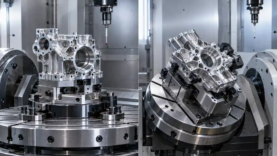
A CNC setup is more than turning a part over. It is the controlled transition between a machine, workholding arrangement, coordinate system, tool set, program state, and inspection approval. Each additional setup adds labor and queue time, but its larger effect may be on datum transfer, tolerance risk, first-piece verification, and scrap exposure.
That is why two shops can quote the same part differently even when their material and cutting speeds are similar. One route may machine five faces in one clamping on a 5-axis center. Another may use three 3-axis setups with soft jaws. A third may turn the part, transfer it to live tooling, and grind one feature. The lowest setup count is not automatically the best route, but every setup should have a clear purpose and a defined way to recover the part coordinate system.
This guide shows buyers and design engineers how to model CNC setup count cost without assuming a universal shop rate. It also explains which drawing and geometry decisions create reorientations and what evidence makes competing quotes comparable.
What Counts as a CNC Setup?
A setup begins when the shop configures a resource for a defined operation and ends when that configuration must be materially changed or re-established. It may include:
- installing and qualifying a vise, chuck, fixture, pallet, collet, soft jaw, or vacuum plate;
- loading or presetting tools;
- locating the workpiece and establishing work offsets;
- loading the correct program and verifying revision;
- proving clearance and safe motion;
- machining and measuring the first acceptable piece;
- documenting offsets, checks, and release status.
Reclamping within the same fixture can still create a new setup if the datum relationship must be re-established. Conversely, an indexed rotary move within a qualified 3+2 program may expose another face without a manual setup. Ask the supplier how it defines the quoted setup boundaries rather than comparing a number alone.
Setup versus operation
An operation is a manufacturing step; a setup is the physical and coordinate-system state in which operations occur. Roughing, finishing, drilling, and tapping can all happen in one setup. One feature may also span several setups—for example, roughing a bore before heat treatment, then finishing it by grinding afterward.
For costing, map both. Operations explain machine and tool time; setups explain preparation, handling, datum transfer, and first-off effort.
The Direct Cost of Each Setup
The direct setup charge generally includes planning, fixture preparation, loading, indicating, offset setting, program verification, and first-piece work. It is largely independent of how many pieces follow in the batch, so it is amortized over quantity.
A simple quote model is:
Average setup cost per piece = total setup-related cost for the batch ÷ accepted batch quantity.
The numerator should include repeated setup activity, not only the machinist’s wrench time. It can include fixture design, soft-jaw machining, probe setup, special tool qualification, first-piece inspection, and documentation. The denominator should reflect expected accepted output, with risk handled transparently rather than hidden through an unexplained unit-price allowance.
At prototype quantity, an extra setup can be a large fraction of unit price. At production quantity, its arithmetic contribution declines, but the recurring handling and tolerance risk may remain. If every piece must be removed, cleaned, re-clamped, indicated, and reverified, much of the work is piece-level rather than batch-level.
Separate Fixed, Per-Batch, and Per-Piece Setup Work
Ask suppliers to classify setup-related effort:
| Cost element | Typical frequency | Examples |
|---|---|---|
| Nonrecurring | New part or major revision | process planning, initial CAM, fixture design, CMM program |
| Per batch/release | Each production run | fixture installation, tool loading, proving, first-off approval |
| Per setup | Each orientation or process state | indicating, work offset, clamp sequence, local inspection |
| Per piece | Every component | manual loading, cleaning locating surfaces, clamping, probing |
| Conditional | Triggered by drift or change | tool replacement, offset correction, requalification, deviation review |
This breakdown reveals why a higher quantity may not dilute every setup expense. It also shows where automation or fixture investment could change the recurring cost.
Datum Transfer Is the Main Technical Risk
When all critical features are machined in one stable clamping, their relationships are established within one machine coordinate system. When the part is reoriented, the next setup must recover position and orientation from physical datum features. Every locating surface, pin, jaw, probe point, chip, burr, and clamping load contributes to that transfer.
The drawing tolerance belongs to the finished part, not to an individual setup. The process planner must allocate enough error budget for machining, workholding, temperature, and measurement across all transfers. A design that locates tightly related features from unrelated faces can force the shop to use additional probing, precision fixtures, grinding, or a different machine architecture.
Questions for each transfer
For every reorientation, ask:
- Which finished or in-process features locate the part?
- Are those features rigid, accessible, clean, and repeatable?
- Were they created in a prior setup with enough accuracy?
- Does clamping distort the part or hide a locating surface?
- How is the work offset established—hard stops, pins, indicating, probing, or qualification artifact?
- Which critical relationships cross the setup boundary?
- How is the first piece verified before the batch continues?
A quote that identifies the setup count but not the datum-transfer strategy is incomplete for a tight-tolerance part.
Fixture and Workholding Changes
Workholding converts setup design into repeatable physical location. A standard vise or collet may be economical for prototypes. Machined soft jaws can support a second operation with moderate repeatability. A dedicated fixture can locate several parts, expose more faces, manage clamping force, and reduce load time. Vacuum, adhesive, magnetic, expanding-mandrel, or custom nests may be appropriate for special geometries.
Each method has cost and constraints. Custom fixtures require design, material, manufacturing, inspection, storage, maintenance, and sometimes spare components. Flexible workholding needs less upfront investment but can require more indicating and operator judgment.
Ask the quote to distinguish:
- standard workholding included in machine/setup cost;
- consumable or part-specific soft jaws;
- dedicated fixture or pallet investment;
- buyer ownership and transfer rights;
- expected fixture life and replacement items;
- qualification and periodic verification;
- storage and preservation between orders.
The fixture should locate the functional datum structure where practical. If it locates a rough or nonfunctional surface, the process must explain how variation is removed before critical features are completed.
Probing, Indicating, and Coordinate Recovery
Probing can reduce manual alignment and verify stock or fixture position, but it does not eliminate error. Probe calibration, stylus geometry, approach direction, surface condition, temperature, and macro logic matter. An in-machine probe may establish a local coordinate system or detect gross loading error; it is not automatically a substitute for final inspection.
Manual indicating can be effective for prototypes and precision work but adds operator time. Hard stops and pins can be fast if locating features and fixture cleanliness are controlled. Qualified pallets can carry a known coordinate system between preparation and machining.
For quotation, the relevant question is how much repeated work occurs per batch and per piece. If every part needs a multi-point alignment routine, include that cycle time. If only the fixture is qualified once and parts load against repeatable datums, separate that fixed effort.
First-Piece Verification Repeats at Setup Boundaries
The first piece after a new setup, fixture installation, program revision, or major tool change often needs additional verification. The shop may inspect the features created in that setup and the relationships carried from earlier setups before releasing the remaining batch.
This first-off activity can involve in-process probing, bench gages, height gages, vision systems, CMM measurement, or functional checks. Its cost depends on characteristic count, accessibility, reporting, and the consequence of proceeding incorrectly.
Define the hold point. The supplier should know whether it may continue after internal approval or must wait for buyer approval. A buyer-witnessed first article can add calendar time even when the inspection itself is short. Put the expected response time in the RFQ.
3-Axis, 3+2, and Simultaneous 5-Axis Alternatives
Machine capability changes the number and nature of setups.
Multiple 3-axis setups
A 3-axis route can be economical and robust when the part has accessible orthogonal faces and sensible datums. Standard machines and fixtures may provide competitive capacity. The tradeoff is manual reorientation and more datum transfers.
Indexed 3+2 machining
With 3+2 machining, rotary axes position the part, then cutting occurs with those axes locked. It can expose several faces in one clamping, shorten tools, and reduce transfer error. It still requires accessible geometry and careful fixture clearance.
Simultaneous 5-axis machining
Simultaneous motion can machine contoured surfaces, undercuts, impellers, and difficult orientations. It can reduce setup count and tool reach, but programming, simulation, collision control, tool-center-point accuracy, and machine cost may be higher. A simple prismatic part does not become cheaper merely because it runs on a 5-axis machine.
Use the process that reduces total risk and cost. The QuickCNCs CNC milling services page describes relevant capabilities; the quote should identify the actual route proposed for the part.
Turning Centers and Mill-Turn Setup Reduction
A conventional turned part may require a first chucking for the main diameter and a second operation to finish the cutoff face. Cross holes, flats, keyways, or off-axis features can add milling or EDM. A live-tool or mill-turn machine may combine several operations, while a subspindle can transfer the part automatically.
Combining work can improve concentricity and reduce handling, but it may introduce transfer conditions between main and subspindles. Bar stock, collet length, part-off allowance, jaw pressure, and slenderness affect the route. Compare the complete process, not the machine label.
For volume work, automation can make a higher-capability machine economical. For a prototype, separate operations on available equipment may have a shorter queue and lower total cost.
Geometry Features That Create Setups
Common setup drivers include:
- features on opposite sides that cannot be reached in one clamping;
- tight relationships between faces that require a common datum;
- deep pockets needing short-tool access from another direction;
- undercuts, back counterbores, internal grooves, or side holes;
- sealing, optical, or bearing features protected from clamping;
- thin walls that cannot support the required force;
- finish-machined datum features unavailable until late in the route;
- heat treatment, coating, grinding, or EDM between machining stages;
- part sizes that exceed rotary, fixture, or machine travel limits.
Mark these features during DFM. Ask the supplier for a setup sketch or route summary showing which features are completed together. The shop can protect proprietary details while still exposing critical transfer boundaries.
DFM Changes That Can Reduce Setup Count
Do not remove a setup by weakening function. Instead, test targeted changes:
- Increase an internal radius to allow access from the primary orientation.
- Move a side hole or add clearance so a standard tool can reach it.
- Replace an undercut with a relieved or assembled feature.
- Align noncritical features to common axes or faces.
- Add a temporary or permanent locating feature where it does not harm function.
- Permit a small witness or clamp area on a nonfunctional surface.
- Change a deep blind feature to a through feature with an approved plug.
- Separate a complex monolithic part into components when assembly risk is acceptable.
- Reassign tolerances so only functionally related features require a common setup.
- Define a larger stock or process tab that supports early operations and is removed later.
Evaluate the whole route. A geometry change that removes machining setup may add assembly, sealing, cleaning, or inspection cost.
Model the Quote with a Setup Map
Create a simple table for each proposed route:
| Setup | Part orientation and locating features | Features completed | Transfer-sensitive requirements | Preparation and first-off evidence |
|---|---|---|---|---|
| 1 | Raw stock on primary fixture | Primary datum, roughing, accessible features | Stock allowance and datum quality | Fixture qualification, probe/offset check, first-off dimensions |
| 2 | Locate from finished primary datum | Opposite face and related pattern | Thickness, parallelism, position to setup 1 | Location check, cross-setup CMM characteristics |
| 3 | Side orientation or rotary index | Cross holes, ports, slots | Position/orientation to datum frame | Probe recovery and feature verification |
| 4 | Secondary process | Grind, EDM, or finish feature | Final size and relation after process | Process certificate and final inspection |
Replace the example with the actual process. Then attach cost frequency: nonrecurring, per batch, per setup, or per piece. This is enough to compare routes without demanding confidential rates.
A neutral cost equation
For one batch:
Batch cost = NRE + fixture/tooling + Σ(setup preparation + first-off verification) + quantity × Σ(load/align + machining + in-process inspection) + outside processing + final release.
Use quoted values rather than invented industry averages. If a design change removes setup 3, compare the avoided preparation, handling, machining, inspection, and risk against any new cost it creates.
Quantity Changes the Best Setup Strategy
For one prototype, flexible workholding and manual alignment may be rational. For 50 recurring parts, soft jaws and a setup sheet can improve repeatability. For thousands of stable parts, multi-part fixtures, pallets, bar feeding, robotics, or a dedicated cell may justify higher NRE.
State order quantity, release quantity, and annual demand. The same total annual volume made in monthly batches repeats fixture loading and first-off approval. A one-time annual run reduces recurrence but increases inventory and revision exposure.
Ask which setup work is amortized over the order and which repeats on every release. Also ask whether fixture cost is included, separately charged, or contingent on a volume commitment.
Tolerance Allocation Across Setups
Tight drawing tolerances should not be divided mechanically by the number of setups. The process owner should build an error budget appropriate to the locating method, machine, cutting process, thermal condition, and measurement.
Relationships completed in one setup can often be controlled more directly. Cross-setup requirements may need stable datum features, probing, precision nests, finish stock, and final measurement in one datum reference frame. If the tolerance cannot accommodate realistic transfer error, options include:
- combine features in one clamping;
- finish both features in a later common setup;
- change the datum or tolerance to match function;
- use grinding, honing, jig grinding, or EDM;
- add an assembly adjustment or selective-fit strategy;
- improve the fixture and verification method.
The design owner must approve requirement changes. The supplier should propose process alternatives and evidence.
Compare Supplier Quotes Fairly
Ask each bidder to provide a high-level route with:
- setup count and machine type for each stage;
- locating datum or feature for every reorientation;
- critical relationships that cross setup boundaries;
- standard, soft-jaw, or dedicated workholding;
- probing or indicating assumptions;
- first-off and final inspection scope;
- NRE, fixture, per-batch, and per-piece cost treatment;
- expected batch size and release cadence;
- exceptions, proposed DFM changes, and approval gates.
Do not choose the route with the fewest setups automatically. A two-setup route with poor support can be riskier than a three-setup route with strong datums. A 5-axis route can reduce transfer error but cost more if capacity is scarce. Compare total delivered cost, schedule, evidence, and repeatability.
Three Route Comparisons to Ask For
Prismatic housing with five machined faces
A prototype route may complete the base and internal pocket in a vise, machine the opposite face in soft jaws, then use two side orientations for ports. An indexed 3+2 route may expose all side ports in the primary clamping and need only a second operation for the base. Compare not only two fewer setups, but also the shorter tools, rotary-fixture clearance, programming effort, and relationship of the ports to the main datum frame.
If port position is loose and quantities are low, the vise route may remain economical. If several port axes have tight true-position requirements to the internal bore, keeping them in one qualified coordinate system can justify the multi-axis route. The drawing should reveal that functional relationship so the supplier does not optimize the wrong feature.
Flanged shaft with cross holes
A conventional route may turn both diameters, reverse the shaft to finish the back face, then move it to a mill for the bolt circle and cross hole. A mill-turn route may complete most features without manual relocation. Compare spindle-transfer accuracy, bar or chuck workholding, live-tool access, burr control at intersecting holes, and how runout is verified after all operations.
For a long flexible shaft, fewer setups do not solve deflection. The route may still need a steady rest, tailstock, follower, intermediate stress relief, or grinding. Cost belongs to the complete stability and inspection plan.
Heat-treated plate with precision bores
A plate may be roughed in one or two setups, heat treated or stress relieved, then re-located for finish milling and bore work. The thermal process creates an unavoidable state change; trying to call the entire route “one setup” would hide the real requalification. Compare stock allowance, datum restoration, straightening limits, final bore process, and the measurement condition.
These comparisons are not case-study claims. They are review patterns that show why the same geometry can support several defensible routes. Ask bidders to connect their chosen route to the released tolerance and quantity.
Prevent Setup Savings from Moving Cost Elsewhere
A proposed setup reduction may create a different cost that is less visible. Combining operations can require a more expensive machine, longer programming and simulation, a complex fixture, special tool extensions, or a slower cycle. A design change can remove a side setup but add a plug, weld, seal, or assembly inspection.
Review the downstream effects on deburring, cleaning, coating, CMM access, packaging, and repair. If an internal cross hole becomes a plugged drilling, define leak integrity and plug retention. If a monolithic part becomes an assembly, evaluate tolerance stack, fasteners, corrosion couples, and serviceability. The saving is valid only when the alternate route preserves the same functional and evidence boundary.
Setup-Count Checklist for the RFQ
Before quotation, confirm:
- The 3D model and controlled drawing show the same revision.
- Functional datums and cross-face relationships are explicit.
- Tight tolerances are assigned only where required.
- The supplier knows the prototype, batch, and annual quantities.
- Heat treatment, finishing, grinding, EDM, and inspection sequence is defined.
- Final dimensions are identified as pre- or post-finish.
- Clamping-sensitive, cosmetic, sealing, and thin-wall surfaces are marked.
- Buyer approval gates and response times are stated.
- Fixture ownership and transfer expectations are included.
- First-article and recurring inspection evidence are comparable across bidders.
- Proposed DFM changes are documented before the quote baseline changes.
Use Setup Count as a Decision Variable
The setup count should explain the manufacturing route, not act as a score. The best route protects functional relationships with the least total work and acceptable risk. It may combine faces on a multi-axis machine, use a simple second operation with reliable soft jaws, or add a precision secondary process for one feature.
When requesting a quote, provide the model, drawing, quantities, material, finishing, tolerance, inspection, and delivery requirements. QuickCNCs can review setup alternatives across CNC milling, turning, and EDM and wire EDM services. Submit the controlled package through the Request a Quote page.
A transparent setup map gives engineering a way to improve the design, gives purchasing a way to normalize cost, and gives quality a way to focus verification on the transfers most likely to consume the tolerance budget.