
Getting your custom parts made perfectly is a constant challenge. A wrong choice in your machining partner or process can lead to costly delays and rework, putting your entire project at risk. Understanding the fundamentals of precision machining is the first step toward getting it right every time.
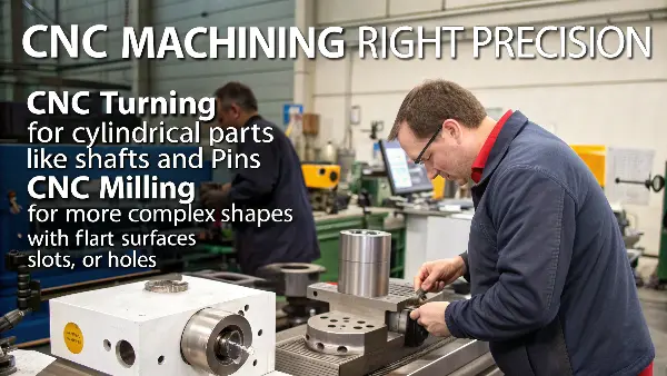
The best way to choose a precision CNC service is to match your part’s geometry to the right process. Use CNC turning for cylindrical parts like shafts and pins, where the material rotates against a cutting tool. For more complex shapes with flat surfaces, slots, or holes, like enclosures or brackets, CNC milling is the right choice, as a rotating tool cuts a stationary workpiece.
Making the right choice between CNC turning and milling seems straightforward on the surface, but the details are what make or break a project. I’ve seen engineers spend too much money because they specified the wrong process, or get unusable parts because the supplier wasn’t truly capable of "precision" work. To help you avoid these issues, we need to look closer at what each service offers and what "precision" really means in practice. Let’s break it down so you can make informed decisions and partner with suppliers who truly understand your requirements.
What’s the Core Difference Between CNC Turning and Milling?
You designed a complex part but are unsure which machining process is most efficient. Choosing the wrong one can inflate your costs or even make the part impossible to produce as designed. That’s a headache none of us need, especially when deadlines are tight.
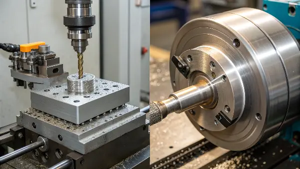
The main difference is in how the material is removed. In CNC turning (lathes), the workpiece rotates rapidly while a stationary cutting tool shapes it, ideal for cylindrical parts. In CNC milling, the cutting tool rotates and moves along multiple axes to cut a stationary workpiece, creating complex shapes, pockets, and holes.
When I first started in a machine shop over a decade ago, this was one of the first lessons I learned. We had a project for a client that involved a set of custom mounting pins and a complex housing. A junior engineer on my team tried to quote the round pins using a 5-axis mill. While technically possible, it was incredibly inefficient. I showed him how a simple CNC lathe could produce those same pins in a fraction of the time and cost. The key is understanding the fundamental mechanics of each process.
This knowledge isn’t just for machinists; it’s critical for design engineers like you. When you understand how a part will be made, you can design it for manufacturability (DFM), which saves time and money down the line. It also helps you have more meaningful conversations with your manufacturing partners.
Let’s look at the specifics of each process a little more closely.
The Dynamics of Each Process
| Feature | CNC Turning (Lathe) | CNC Milling (Mill) |
|---|---|---|
| Primary Motion | Workpiece rotates | Cutting tool rotates |
| Typical Part Shape | Cylindrical, conical, round (shafts, pins, bushings) | Prismatic, complex, flat (blocks, plates, housings) |
| Tool Type | Single-point cutting inserts | Multi-point rotating cutters (end mills, drills) |
| Axes of Motion | Typically 2-axis (X, Z) | 3, 4, or 5-axis (X, Y, Z + rotational axes) |
| Common Uses | Creating symmetrical round features | Creating pockets, slots, holes, and complex surfaces |
Understanding this table helps you mentally map your design to a machine. If you’re designing a driveshaft, you should immediately think "lathe." If it’s a custom electronics enclosure, you’re in the world of milling.
What Makes CNC Machining Truly "Precision"?
Every supplier claims to offer "precision" machining, but the results often fall short. You receive parts with dimensions out of spec, poor surface finishes, or inconsistencies across a batch. This forces you into difficult conversations and can derail your project timeline, eroding trust in your supply chain.
True precision machining is defined by three key factors: tight and repeatable tolerances (typically ±0.01mm or better), superior surface finish (often Ra 0.8μm or lower), and consistent quality across every part. This is achieved through high-end machines, skilled machinists, and a robust quality control process, not just promises on a website.
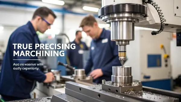
I remember working with a German robotics client, an engineer much like Alex. He needed a set of gear components with a tolerance requirement of ±0.005mm. Many shops we initially contacted said "no problem," but only a few could show proof of their capabilities. The one we chose didn’t just have the best 5-axis machines; they had a temperature-controlled inspection room with CMMs (Coordinate Measuring Machines) calibrated weekly. That’s the level of commitment that separates "precision" from just "machining." It’s not just about what the machine can do, but the entire ecosystem of quality assurance that supports it.
This is a critical point to consider when you’re evaluating a new supplier. Don’t be afraid to ask the hard questions.
Key Pillars of Precision
To achieve genuine precision, a shop must excel in several areas. Here’s what you should be looking for:
1. Advanced Machinery and Tooling
The machine itself is the foundation. A low-cost, aging 3-axis mill will never hold the same tolerances as a modern, well-maintained 5-axis machining center from a brand like DMG Mori or Haas. Thermal stability, rigidity, and high-quality spindles are non-negotiable for ultra-fine work. The same goes for tooling—using premium, sharp cutting tools is essential for achieving a fine surface finish and holding tight dimensions.
2. Skilled Programming and Operation
A great machine is useless without a skilled programmer and machinist. Expert CAM programming is needed to create efficient and precise toolpaths. The machinist on the floor needs the experience to understand how different materials react, make micro-adjustments during the run, and troubleshoot issues in real-time. This human element is often the most overlooked part of precision.
3. Rigorous Quality Control
This is where promises are verified. A true precision shop will have a dedicated quality department with the right inspection tools. This includes:
- Calipers and Micrometers: For basic checks.
- Height Gauges and Bore Gauges: For more specific dimensional checks.
- Coordinate Measuring Machine (CMM): The gold standard for verifying complex geometries and tight tolerances.
- Surface Roughness Testers: To quantify the surface finish (Ra value).
Without this level of inspection, a supplier is just guessing. You should always ask for a First Article Inspection (FAI) report with any new part order to confirm they can meet your specs before starting full production.
When Should You Choose Turning Over Milling (and Vice Versa)?
You’ve designed a part with both round and blocky features. Now you face a decision: should it be made primarily on a lathe or a mill? Or does it need both? This uncertainty can lead to over-engineering the production plan, resulting in higher costs and longer lead times.
Choose CNC turning as the primary operation for any part that is predominantly cylindrical. Even if it has some milled features like flats or cross-holes, starting on a lathe is more efficient. Choose milling for parts that are mainly prismatic or block-shaped. For parts with significant features of both types, a multi-axis turn-mill center is the most efficient solution.
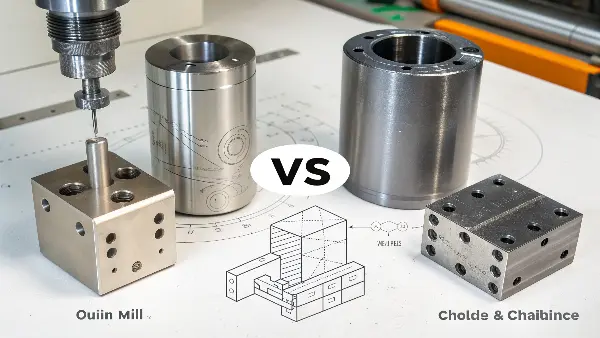
I once consulted for a startup building a new type of drone. They had designed a motor mount that was essentially a cylindrical hub with complex, lightweighted mounting arms branching off it. Their initial quotes were very high because they specified it as a pure 5-axis milling job. I took one look at the design and suggested a different approach. We started by turning the main hub profile from round bar stock on a CNC lathe—a fast and cheap process. Then, we moved the turned blank to a 4-axis mill to create the arms. This two-step process cut the total machining time by nearly 40%, leading to a huge cost saving for the client.
This "process optimization" is a key service a good manufacturing partner provides. They should be able to analyze your design and recommend the most effective production strategy.
A Decision-Making Framework
Making the right choice often comes down to identifying the primary geometry of your part. Let’s break it down with a simple guide.
Scenario 1: Primarily Cylindrical Parts
If your part is a shaft, pin, axle, nozzle, or has a dominant rotational symmetry, always start with turning.
- Simple Cylinders: Use a 2-axis CNC lathe. This is the most cost-effective method for round parts.
- Cylinders with Off-Center Features: If your shaft needs a flat face (a "D-cut"), a keyway, or cross-drilled holes, you have two options:
- Two Operations: Turn the main profile on a lathe, then move it to a mill for the secondary features. This is common and effective.
- Turn-Mill Center: Use a ‘mill-turn’ or ‘multi-axis’ lathe that has live tooling. This machine can perform both turning and milling operations in a single setup, which is ideal for high-volume production or very complex parts as it improves accuracy by reducing setup errors.
Scenario 2: Primarily Prismatic Parts
If your part is a block, plate, bracket, or enclosure, milling is your starting point.
- Simple 2.5D Features: For parts with pockets, holes, and features all on parallel planes, a 3-axis mill is perfect and cost-effective.
- Complex Surfaces and Angled Holes: For parts with curved surfaces (like molds) or features on multiple faces, you’ll need a 4-axis or 5-axis mill. 5-axis milling can machine highly complex parts in a single setup, offering the best accuracy for intricate designs.
Thinking in these scenarios as you design will help you create parts that are not only functional but also economical to produce.
How Do These Choices Impact Your Project’s Cost and Lead Time?
As an engineer, you’re focused on function and precision, but management is always asking about the bottom line. How can you justify your design and manufacturing choices when it comes to cost? Making a suboptimal process choice can easily double your part cost and add weeks to your lead time.
Your choice between turning and milling directly impacts cost. Turning is generally cheaper and faster for round parts due to simpler setups and lower machine time. Milling, especially 5-axis, is more expensive due to complex programming, longer cycle times, and higher machine costs. Minimizing setups by using multi-axis machines or designing for a single process is key to controlling costs.

A few years ago, a client came to me with a design for an aluminum housing. It was a beautiful, organically curved part that screamed "5-axis milling." The quotes they were getting were astronomical. We sat down and looked at the design’s core functional requirements. By slightly modifying some non-critical radii and changing a few curved surfaces to be machinable with a 3-axis mill and a single angled setup, we kept 99% of the part’s function but reduced the estimated machining time by over 60%. The cost savings were immense, and it turned a "no-go" project into a successful product launch. This highlights a crucial lesson: the biggest factor in cost is often the design itself.
A good manufacturing partner will help you find these opportunities for cost savings without compromising the part’s integrity.
Breaking Down the Cost Drivers
Let’s examine the specific factors that influence the final price of your machined part.
| Cost Driver | Impact on Turning | Impact on Milling | How to Optimize |
|---|---|---|---|
| Material | Round bar stock is common and often cheaper. Less waste for round parts. | Starts from a block, which can lead to more wasted material. | Choose the stock size closest to your final part dimensions. |
| Machine Time | Very fast for simple profiles. Cycle times are usually short. | Can be very long, especially for complex 3D surfacing in 5-axis work. | Simplify your design. Can a curved surface be flat? Can you reduce the number of small features? |
| Programming | CAM programming is relatively simple for 2-axis lathes. | 3-axis is more complex; 5-axis programming is highly skilled and time-consuming. | Design with standard tool sizes in mind. Avoid deep, narrow pockets that require special tooling. |
| Setups | A single setup is common. Live tooling can eliminate second-op milling setups. | Multiple setups are often needed for 3-axis work, increasing labor and risk of error. | Design parts to be machined from as few sides as possible. Consolidate features to one or two faces. Use 5-axis for complex parts to machine in one setup. |
| Tolerances | Holding tight tolerances on diameters is standard. | Holding tight positional tolerances between features is more complex. | Only specify tight tolerances where they are functionally necessary. Looser tolerances on non-critical features save a lot of money. |
By considering these drivers during the design phase, you can proactively reduce costs. A simple question like, "Can this feature be made on a lathe instead of a mill?" can save you thousands of dollars over the lifetime of a product. Always discuss these factors with your supplier; their feedback is invaluable.
Conclusion
Choosing the right CNC service comes down to matching part geometry to the right process—turning for round parts and milling for complex ones—and partnering with a supplier who truly delivers precision.