Struggling with part validation? Traditional tools failing on complex geometries? Ultra-precision demands advanced measurement. Learn how modern techniques ensure your CNC parts are perfect.
Advanced measurement for ultra-precision CNC parts uses tools like CMMs, laser scanners, and optical interferometers. These methods offer high-accuracy inspection of internal and external features, ensuring dimensional integrity for complex components. Techniques like CT scanning and GR&R analysis are also vital.
Ensuring the quality of ultra-precision CNC parts is a big challenge. I see it every day. Engineers like Alex need parts with tolerances sometimes in the single microns. Old-school calipers and micrometers just cannot give the full picture for such complex components. At QuickCNCs, we rely on advanced measurement techniques. These not only confirm dimensions but also give us deeper insights into the manufacturing process itself. Let us explore some key methods.
How Do Coordinate Measuring Machines (CMMs) Guarantee Part Accuracy Down to the Micron?
Are manual checks too slow? Doubting if your complex parts meet tight tolerances? CMMs provide automated, highly accurate 3D measurements.
Coordinate Measuring Machines (CMMs) use a probe to touch multiple points on a part. Software then constructs a 3D model, comparing it against the CAD data to verify dimensions with exceptional precision.
Coordinate Measuring Machines, or CMMs, are the workhorses of modern metrology. I have relied on them for years to verify the accuracy of critical parts. Think of a CMM as a very precise robot. It has a probe that can move in three dimensions (X, Y, and Z axes). This probe touches the part at various programmed points. The machine records the coordinates of each touch point. Sophisticated software then takes these points. It creates a digital representation of the part. This digital twin is then compared to the original 3D CAD model.
There are different types of CMMs.
CMM Types and Features:
| Feature | Description | Common Use |
|---|---|---|
| Bridge CMMs | Most common type. The bridge moves along one axis, the carriage along another, and the quill (with probe) up/down. | General purpose, wide range of part sizes. |
| Gantry CMMs | Similar to bridge, but larger. Suited for very large and heavy parts. | Automotive body panels, large aerospace components. |
| Arm CMMs | Portable, articulated arms with a probe at the end. Offer flexibility. | On-machine inspection, large parts that cannot be moved to a CMM lab. |
| Probe Types | Touch-trigger probes take discrete points. Scanning probes drag along surfaces for continuous data. | Touch-trigger for geometric features. Scanning for profiles and surfaces. |
CMMs can measure almost any geometric feature: holes, slots, planes, cylinders, cones, and complex surfaces. For Alex’s robotic arm components, which often have intricate profiles and tight positional tolerances between features, a CMM is essential. It gives us the confidence that every critical dimension is within spec. Regular calibration of the CMM itself is also very important to maintain its accuracy.
Can Laser Scanners Capture Every Detail of Complex CNC Parts?
Manual inspection taking too long? Worried about missing fine details on freeform surfaces? Laser scanners offer rapid, comprehensive 3D data capture.
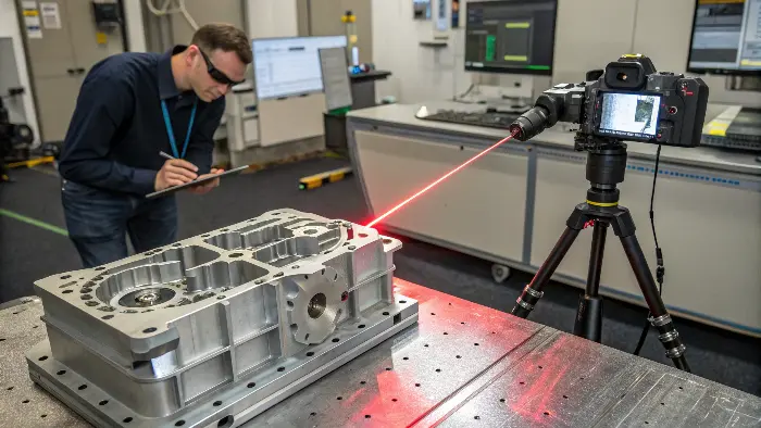
3D laser scanners project a line or pattern of laser light onto a part. A camera captures the deformation of this light. Software then calculates millions of 3D data points, creating a dense "point cloud" model.

When we need to inspect a whole surface quickly, especially for parts with complex, organic shapes, 3D laser scanning is a fantastic tool. I have seen it save huge amounts of time compared to traditional methods. Instead of just taking a few points like a CMM might initially, a laser scanner captures millions of points in seconds. This creates what we call a "point cloud." It is like a digital duplicate of the part’s surface.
There are a few main types of laser scanning technologies.
- Laser Triangulation: A laser line is projected onto the part. A camera, offset at a known angle and distance, sees how this line deforms over the part’s surface. Simple trigonometry then calculates the 3D coordinates. This is great for high accuracy on smaller parts.
- Structured Light Scanning: Instead of a line, a pattern of light (like stripes or grids) is projected. Cameras capture how this pattern wraps around the object. This method is very fast and can capture color texture too.
- Time-of-Flight (LIDAR): This sends out a pulse of laser light. It measures the time it takes for the light to hit the surface and return. This is better for very large objects or longer distances.
Once we have the point cloud, specialized software processes it. We can align it to the CAD model for a color-coded deviation map. This instantly shows where the part is over or under size. Alex finds this very useful for first article inspections of new housing designs, as it gives a complete surface check. It is also used for reverse engineering if we need to create a CAD model from an existing part.What Makes Optical Interferometry Ideal for Super-Smooth Surface Finish Measurement?
Are your parts’ surface finishes critical for performance? Need to measure roughness down to the nanometer? Optical interferometry provides unmatched precision for surface topography.
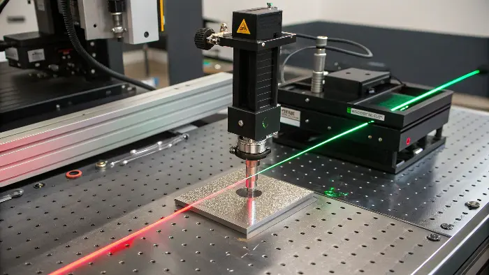
Optical interferometers use the principle of light wave interference. They split a beam of light, reflect one part off a reference surface and the other off the test surface, then recombine them to create an interference pattern. This pattern reveals surface height variations with extreme accuracy.

For some applications, like optical components, high-performance bearings, or sealing surfaces, the surface finish is incredibly important. We are not just talking about how shiny it looks. We are talking about microscopic peaks and valleys. These can affect friction, wear, light reflectivity, or sealing ability. When we need to measure these ultra-smooth surfaces with nanometer-level precision, optical interferometry is the go-to technique. I have used it for clients in the medical device and semiconductor industries.
It is a non-contact method, which is a big advantage. It does not risk damaging delicate surfaces.How Optical Interferometry Works:
- Light Splitting: A beam of light from a coherent source (like a laser or specialized lamp) is split into two beams.
- Reflection: One beam (the reference beam) is directed to a perfectly flat reference mirror. The other beam (the measurement beam) is directed to the surface of the part being tested.
- Recombination: The two reflected beams are brought back together.
- Interference Pattern: If there are differences in the path length traveled by the two beams (caused by height variations on the test surface), they will interfere with each other. This creates a pattern of light and dark fringes.
Sophisticated software analyzes these fringe patterns. It can generate a 3D map of the surface topography. From this map, we can calculate various surface finish parameters like Ra (average roughness), Rz (average maximum height of the profile), and others. For Alex, if he were designing a very high-precision air bearing, the surface finish of the mating parts would be critical. Optical interferometry would be the only way to truly verify it.How Does CT Scanning Reveal Hidden Flaws in Precision Components?
Worried about internal defects you cannot see? Need to check complex assemblies without taking them apart? X-ray CT scanning provides non-destructive 3D internal inspection.
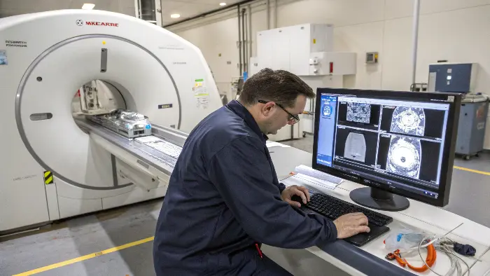
X-ray Computed Tomography (CT) scanning works like medical CT. It takes hundreds or thousands of 2D X-ray images from different angles around a part. A computer then reconstructs these into a 3D model, showing both external and internal structures.

Sometimes, the most critical features or potential flaws are hidden inside a part. This could be porosity in a casting, cracks that have not reached the surface, or the internal geometry of a complex, additively manufactured component. Taking the part apart or cutting it open for inspection is destructive. This is where industrial X-ray CT scanning comes in. I have found it invaluable for troubleshooting and quality assurance of high-value or safety-critical parts.
The process is amazing. The part is placed on a rotating stage between an X-ray source and a detector. As it rotates, X-rays pass through it, and the detector captures images. Denser materials absorb more X-rays. The software then uses complex algorithms to build a 3D volumetric dataset. We can slice through this dataset digitally in any direction. We can see internal voids, inclusions, wall thicknesses, and even check the assembly of internal components. For Alex’s robotic systems, if there was a suspected internal crack in a critical joint component made through casting or 3D printing, CT scanning would be the way to find it without destroying the part. It can also be used for dimensional metrology of internal features that are impossible to reach with CMMs or scanners.Why Is Gage R&R Crucial for Validating Your Measurement System?
Getting inconsistent measurements? Different operators getting different results? Gage Repeatability & Reproducibility (GR&R) studies tell you if your measurement system itself is reliable.
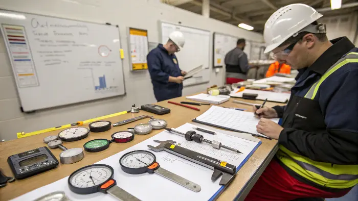
A Gage R&R study quantifies the amount of variation in your measurement system. It separates variation due to the measurement instrument (repeatability) from variation due to different operators using the instrument (reproducibility).

Having the most advanced measurement equipment is great. But if the measurement process itself is flawed, your results will not be trustworthy. This is where Gage Repeatability and Reproducibility (GR&R) studies come in. I always recommend these studies, especially when setting up new measurement processes or when troubleshooting inconsistencies. Alex and his team implemented GR&R after noticing some discrepancies in measurements between shifts.
A GR&R study helps us understand how much of the observed variation in measurements is actually due to the parts, and how much is due to the measurement system.
- Repeatability is the variation you see when the same operator measures the same part multiple times with the same gage. It tells you about the inherent variation in the gage itself.
- Reproducibility is the variation you see when different operators measure the same part multiple times with the same gage. It tells you about the variation caused by differences in operator technique.
Conducting a Basic GR&R Study:
Step Action Purpose 1. Select Parts Choose 5-10 parts that represent the typical process variation. To capture the range of expected measurements. 2. Select Operators Choose 2-3 operators who normally perform the measurement. To assess inter-operator variability. 3. Measure & Record Each operator measures each part 2-3 times, in random order. To collect data for statistical analysis. 4. Analyze Data Use statistical methods (ANOVA is common) to calculate R&R percentages. To quantify repeatability, reproducibility, and overall system error. Generally, if the total GR&R variation is less than 10% of the part tolerance, the measurement system is considered acceptable. If it is between 10% and 30%, it might be acceptable depending on the application’s criticality. Above 30% means the system needs improvement. This systematic approach ensures that when we say a part is in spec, we are confident in that statement.
Conclusion
Advanced measurement techniques like CMMs, laser scanners, interferometers, and CT scans are key for ultra-precision parts. GR&R studies ensure your measurement process itself is reliable and accurate.
