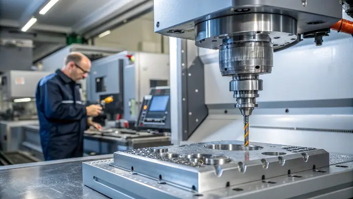
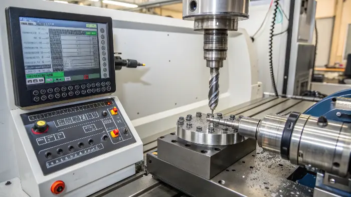
Struggling with complex parts? Unsure if your software can handle demanding materials like titanium? Getting the right software is key to precision and efficiency in CNC machining.
Choosing the correct Computer-Aided Design (CAD), Computer-Aided Manufacturing (CAM), and machine control software is crucial. This suite ensures accurate design translation, optimal toolpaths, and precise execution, especially for challenging materials like aluminum and titanium, leading to quality parts.
When I first started in a CNC shop, the software seemed like a black box. But over the years, helping clients like Alex bring their high-tolerance designs to life, I’ve learned that the right software isn’t just helpful; it’s fundamental. It bridges the gap between a brilliant design on screen and a perfectly machined part in your hand. Let’s explore what you really need to get those aluminum and titanium components right every time. You’ll want to understand these details to avoid costly mistakes.
What Software Is Generally Needed for Any CNC Machine Operation?
Feeling overwhelmed by CNC software options? Wondering what the basic toolkit even looks like? Getting the right software foundation is your first step to successful machining.
Typically, you need three types of software: CAD for design, CAM for generating machine instructions (G-code), and control software on the CNC machine itself to interpret these instructions and move the tools.
When we talk about CNC machining, whether it’s for a simple bracket or a complex aerospace part, a few software categories are always involved. I’ve seen many engineers, especially those new to outsourcing, get confused here. So, let’s break it down simply.
Core Software Types for CNC Machining
| Software Type | Primary Function | Key Considerations for Aluminum & Titanium | My Experience |
|---|---|---|---|
| CAD (Computer-Aided Design) | Creating 2D or 3D models of the part. | Ability to handle complex geometries, good import/export features. | Most engineers like Alex use SolidWorks, AutoCAD, or Fusion 360. The key is a clean, well-defined model. |
| CAM (Computer-Aided Manufacturing) | Translating CAD models into G-code (toolpaths). | Advanced toolpath strategies (e.g., HSM), good post-processor, simulation. | This is where the magic happens for machinability. For titanium, precise CAM settings are non-negotiable. |
| Control Software / Firmware | Interpreting G-code and operating the CNC machine. | Compatibility with CAM output, real-time monitoring. | This is usually specific to the machine builder (e.g., Fanuc, Siemens, Haas). We ensure our CAM output matches. |
I remember a project for a robotics company; the initial G-code from a less sophisticated CAM system caused tool chatter on a titanium joint. We switched to a CAM package with better trochoidal milling paths, and the finish improved dramatically. The control software on the machine simply executed what it was told, so the CAM quality was paramount. Ensuring these three software types work seamlessly together is fundamental.
Can Titanium Actually Be CNC Machined Effectively?
Heard titanium is tough? Worried it’s too difficult for CNC machining? Many engineers ask me this, especially when considering it for demanding applications.
Yes, titanium can be CNC machined very effectively. However, it requires specific knowledge, tooling, and machine parameters due to its unique properties like low thermal conductivity and high strength.

Absolutely, titanium is a regular player in our CNC shops at QuickCNCs. I’ve worked on countless titanium parts, from medical implants to aerospace components. The myth that it’s "unmachinable" is just that – a myth. However, it’s not as straightforward as machining aluminum. Its properties demand respect and a tailored approach.
Key Considerations for Machining Titanium
- Low Thermal Conductivity: Heat doesn’t dissipate quickly through the material. Instead, it concentrates in the cutting zone and the tool. This can lead to rapid tool wear if not managed.
- High Strength at Elevated Temperatures: Titanium retains its strength even when hot, which means more cutting force is needed.
- Chemical Reactivity: At high temperatures, titanium can react with cutting tool materials, leading to built-up edge (BUE) and tool failure.
- Work Hardening: Titanium has a tendency to harden during machining, making subsequent cuts more difficult.
I recall a client, an engineer much like Alex, who was hesitant about using Grade 5 titanium for a robotic arm component due to past experiences with another supplier who struggled. We showed him how the right speeds, feeds, sharp tooling, and copious high-pressure coolant made all the difference. It’s about understanding the material’s behavior and adapting the machining strategy, often driven by sophisticated CAM software, to accommodate it. So, yes, with the right expertise and tools, CNC machining titanium is very feasible.What Specifics Do You Need to Successfully Machine Titanium?
Know titanium is machinable but unsure what’s really required? Getting the setup right is crucial. It’s more than just hitting ‘start’ on the machine.
To machine titanium, you need rigid CNC machines, sharp carbide tools (often coated), high-pressure coolant, and optimized CAM strategies involving lower cutting speeds and consistent feed rates.

Machining titanium isn’t like working with aluminum where you have a wider margin for error. From my experience, success with titanium hinges on a combination of factors, and your CAM software plays a vital role in programming these. Let’s detail what I mean:
Essential Elements for Titanium Machining
| Element | Specification/Requirement | Why it’s Important for Titanium | Software Implication (CAM) |
|---|---|---|---|
| Machine Rigidity | High stiffness, minimal vibration. | Resists cutting forces, prevents chatter, which is detrimental to tool life and surface finish. | Not directly software, but CAM must account for machine capabilities. |
| Cutting Tools | Sharp, positive rake, specific carbide grades (e.g., C2-C4), PVD coatings (TiAlN). | Reduces cutting forces, resists heat and chemical reaction, prolongs tool life. | Tool library in CAM must have accurate tool data. |
| Coolant | High-pressure (over 1000 psi if possible), high volume. | Flushes chips, cools tool and workpiece effectively, prevents heat buildup. | CAM strategies might include paths that maximize coolant access. |
| Cutting Parameters | Lower cutting speeds (e.g., 60-150 SFM), consistent, higher feed rates. | Manages heat generation, prevents work hardening, ensures good chip evacuation. | CAM software must allow precise control over speeds, feeds, depth of cut, and tool engagement. |
| Toolpaths | Trochoidal milling, peel milling, constant tool engagement strategies. | Minimizes heat, reduces tool load variation, improves chip control. | Advanced CAM packages offer these specialized toolpaths crucial for titanium. |
I remember a specific project involving thin-walled titanium housings. The initial attempts with standard toolpaths led to warping due to heat. We then utilized a CAM feature for adaptive clearing with very controlled radial engagement. This, combined with through-tool coolant, solved the problem. It highlighted how critical both the machine setup and the intelligence programmed via CAM software are for titanium. Alex, with his need for high-tolerance parts, would appreciate this level of detail.
What Is the Typical CNC Tolerance Achievable for Aluminum?
Designing aluminum parts and need to know achievable precision? Understanding tolerances is key for functionality and cost. It’s a common question from engineers.
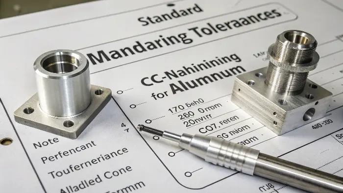
Standard CNC machining tolerances for aluminum are typically around ±0.005 inches (±0.127mm). However, tighter tolerances like ±0.001 inches (±0.025mm) or even ±0.0005 inches (±0.0127mm) are achievable with precision machining.

Aluminum is a fantastic material for CNC machining – it’s generally easy to cut, offers a good strength-to-weight ratio, and allows for excellent surface finishes. When clients like Alex, who demand tight tolerances (±0.01mm or better), ask about aluminum, I tell them it’s very achievable, but several factors come into play. Your CAD and CAM software are instrumental in defining and achieving these.
Factors Influencing Aluminum CNC Tolerances
| Factor | Impact on Tolerance | How Software Helps (CAD/CAM) | My Insight |
|---|---|---|---|
| Machine Capability | Accuracy, rigidity, thermal stability of the CNC machine. | CAM must generate G-code that respects the machine’s limits. Simulation can predict potential issues. | We use well-maintained, high-precision machines. You can’t achieve tight tolerances on a worn-out machine. |
| Material Grade/Alloy | Different aluminum alloys have varying machinability and thermal expansion rates. | Material properties can be input into some CAM systems for better toolpath optimization. | 6061-T6 is common and predictable. 7075-T6 is stronger but can have more internal stress, potentially affecting stability. |
| Part Complexity & Size | More complex features or larger parts can be harder to hold tight tolerances across. | CAD for clear feature definition. CAM for smart toolpaths that minimize stress and tool deflection. | For intricate parts, we often plan multiple setups or use 5-axis machines, programmed carefully with CAM. |
| Tooling & Workholding | Sharpness, tool material, runout, and fixture rigidity. | CAM helps select appropriate tools and cutting parameters. | Quality tooling and robust workholding are non-negotiable. I’ve seen tolerances lost simply due to a part shifting in the fixture. |
| Cutting Strategy | Speeds, feeds, depth of cut, finishing passes. | CAM software is essential for defining roughing and finishing passes to achieve the desired surface and tolerance. | We often use a light finishing pass with a fresh tool for critical dimensions. This is programmed in CAM. |
For a recent project requiring ±0.01mm on several bores in an aluminum housing for a robotic joint, our CAM software’s ability to define precise boring cycles and compensate for tool wear was crucial. CAD models must clearly specify these tolerances using GD&T (Geometric Dimensioning and Tolerancing) so the CAM system and machinist know exactly what’s required.
Conclusion
Selecting the right CAD, CAM, and control software is fundamental for machining aluminum and titanium, ensuring precision, efficiency, and overcoming material-specific challenges effectively.
