Feeling overwhelmed by your first CNC project? Worried about complex software or costly mistakes? This guide makes it easy, even with free tools.
Setting up your first CNC project involves designing your part (CAD), generating toolpaths with CAM software (often free for hobbyists), creating G-code, preparing your CNC machine, and then running the program carefully. It’s a clear process.
Starting with CNC machining can feel like a big leap. I remember my first time; the machine looked intimidating, and the software seemed complex. But once I broke it down, it all clicked. I want to share that clarity with you. Let’s walk through this together, step by step, so you can get your machine cutting with confidence. You’ll see it’s very manageable.
How to make a CNC program step by step, especially with free tools?
Does creating a CNC program seem like a dark art? Afraid of getting lost in code? It’s actually a logical sequence from design to machine instructions.
You make a CNC program by first creating a 3D model (CAD). Then, you use CAM software to define your material, select tools, and plan cutting operations. Finally, the CAM software generates the G-code instructions for your machine.
Creating a CNC program might sound technical, but it’s quite straightforward once you understand the flow. I’ve guided many engineers, like Alex from Germany who needs high-tolerance parts, through this.
It all starts with your design.
- CAD (Computer-Aided Design): First, you need a digital model of the part you want to make. You can use software like Fusion 360 (which has a free license for personal use), FreeCAD (completely open-source), or other professional CAD tools. This model is your blueprint. For Alex, this stage is critical because his robotic components demand precision from the very start.
Next, you move to CAM (Computer-Aided Manufacturing). This is where free software truly shines for beginners and hobbyists. - Import Model: You’ll import your CAD model into the CAM software.
- Setup:
- Define Stock: Tell the software the size and type of your raw material.
- Orient Part: Position your part within the stock.
- Operations & Toolpaths: This is the core of CAM.
- Choose Tools: Select virtual cutting tools (end mills, drills, etc.) from a library or define your own. Alex needs to ensure these match his physical tools for achieving ±0.01mm tolerances.
- Select Machining Strategies: You’ll choose operations like:
- Facing: To make the top surface flat.
- Pocketing: To remove material from an internal cavity.
- Contouring: To cut the outside shape.
- Drilling: To make holes.
- Set Parameters: For each operation, you define speeds, feeds, depth of cut, and step-over. Getting these right is key for good surface finish and tool life.
- Simulate: ALWAYS simulate the toolpaths. The software will show you an animation of the cutting process. This helps you catch errors, potential collisions, or areas where the tool might not reach. It’s a huge time and material saver. I always tell people, "Simulate twice, cut once!"
- Post-Process: Once you’re happy with the simulation, you’ll "post-process" the operations. The CAM software uses a "post-processor" specific to your CNC machine’s controller to translate your toolpaths into G-code. This G-code file is what the CNC machine understands.
Free CAM options like the manufacturing workspace in Fusion 360 (for personal use) or the Path Workbench in FreeCAD are powerful enough for many first projects and even some professional work. I’ve seen amazing things made with them.What is the basic programming of CNC, and is it hard to learn?
Does G-code look like a secret language? Worried you need to be a programmer? The basics are simpler than you think and very logical.
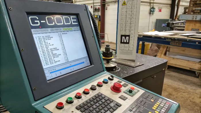
Basic CNC programming is G-code. It’s a set of instructions telling the machine where to move (G commands for geometry) and what to do (M commands for machine functions). You don’t usually write it by hand for complex parts.

When I first saw a G-code file, it looked like a jumble of letters and numbers. But it’s actually the fundamental language your CNC machine speaks. Think of it like a script for your machine to follow. Alex, with his engineering background, appreciates this direct instruction set, especially when troubleshooting or needing fine control for his precision parts.
Essentially, CNC programming boils down to two main types of codes:
- G-codes (Preparatory Codes): These tell the machine about ageometry or motion. They prepare the machine for a certain type of movement or operation.
G00: Rapid move (get from A to B quickly, not cutting).G01: Linear move (straight line cutting at a defined feed rate).G02: Circular move, clockwise.G03: Circular move, counter-clockwise.G28: Return to machine home position.G90: Absolute programming (all coordinates are from the part’s origin).G91: Incremental programming (coordinates are from the last point). Most CAM software outputs G90.
- M-codes (Miscellaneous Codes): These control auxiliary machine functions.
M00: Program stop (machine pauses, operator needs to resume).M02orM30: Program end (resets machine).M03: Spindle start, clockwise.M04: Spindle start, counter-clockwise.M05: Spindle stop.M06: Tool change (often followed by a Tnumber for the tool).M08: Coolant on.M09: Coolant off.
A typical line of G-code might look like this:N10 G01 X10.5 Y25.0 Z-2.0 F150 S1200 T01 M03
N10: Line number (optional, but good for readability).G01: Linear cut.X10.5 Y25.0 Z-2.0: Target coordinates.F150: Feed rate (e.g., 150 mm/minute).S1200: Spindle speed (e.g., 1200 RPM).T01: Tool number 1.M03: Spindle on clockwise.
The good news is, for most projects, your CAM software writes this G-code for you. You don’t need to memorize all these codes to get started. However, understanding the basics helps you read the code, troubleshoot issues, and appreciate what your machine is doing. It’s like knowing basic grammar even if you use a word processor to write.How do I set up my CNC machine for the first cut?
Is the thought of setting up the actual machine scary? Worried about making a costly mistake? A careful, step-by-step setup ensures safety and success.
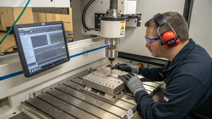
Machine setup involves: securely clamping your workpiece, installing the correct cutting tool, setting your X, Y, and Z zero points (work offsets) on the material, and loading your G-code program. Always double-check everything before pressing start.

This is where the digital plan meets physical reality. It’s an exciting step! I always stress to clients like Alex, who value precision and risk reduction, that a meticulous setup is non-negotiable. Rushing here can lead to broken tools, scrapped parts, or even machine damage.
Here’s a general process I follow:
- Safety First! This is paramount.
- Wear safety glasses.
- No loose clothing, hair tied back.
- Know where your E-Stop (Emergency Stop) button is and make sure it works. I once had a small programming error early in my career, and the E-stop saved me from a bigger problem.
- Prepare the Machine:
- Clean the machine bed and vise/clamps. Chips or debris can affect accuracy.
- Secure the Workpiece (Stock Material):
- Use a vise, clamps, or other fixtures appropriate for your material and part.
- Ensure it’s held very securely. Any movement during machining will ruin the part and could be dangerous. For Alex’s high-tolerance robotic parts, this rigidity is absolutely critical.
- Install the Cutting Tool:
- Select the correct tool as specified in your CAM program (e.g., T01).
- Insert it into the correct tool holder and secure it in the spindle.
- If your machine uses tool length offsets, measure the tool and input the value. Many modern machines or control software handle this semi-automatically.
- Set Work Offsets (X, Y, Z Zero):
- This is crucial. You need to tell the machine where the origin (0,0,0 point) of your CAM program is located on your physical stock material.
- X and Y Zero: Often, this is a corner of the stock or the center of a feature. You can use an edge finder, a probe, or even the "paper test" (carefully jogging the tool towards the edge until it just grips a thin piece of paper).
- Z Zero: This is usually the top surface of the stock. Again, a probe, Z-axis touch plate, or the paper test can be used.
- Once found, you save these coordinates into your machine’s work offset register (e.g., G54, G55).
- Load the G-code Program:
- Transfer your G-code file (generated by your CAM software) to the machine, usually via USB or network.
- The "Air Cut" or Dry Run:
- Set your Z-axis well above the part.
- Run the program. Watch the machine go through the motions. This helps you visually confirm the toolpaths and check for any unexpected rapid moves or crashes before cutting material. This is a step Alex never skips for his complex components.
- First Cut:
- Bring the Z-axis closer, but perhaps not to full depth for the very first pass.
- Reduce the feed rate override on your machine (e.g., to 25-50%).
- Start the program and watch carefully. Listen to the machine.
- If all looks good, you can gradually increase the feed rate override back to 100%.
This careful setup process builds confidence and ensures your first CNC project is a success, not a source of frustration.Conclusion
Setting up your CNC project is a journey from idea to physical part. Follow these steps for design, CAM, G-code, and machine setup. Free software makes it accessible.
