Are you an engineer struggling to get your CNC machined parts made on time and within budget? It’s a common frustration when complex designs lead to manufacturing headaches and unexpected costs. But what if there was a clear methodology to avoid these pitfalls and streamline your production?
Yes, Design for Manufacturability (DFM) for CNC machining is a systematic approach to designing parts that are easier, faster, and more cost-effective to produce. By considering manufacturing limitations and capabilities early in the design phase, you can significantly reduce waste, shorten lead times, and improve the overall quality of your components.
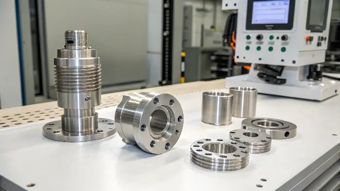
As someone who started on the CNC shop floor and now helps engineers like Alex in Germany source precision parts, I’ve seen countless times how DFM principles can transform a project from a struggle to a success. It’s not just about making a part; it’s about making it smartly. Let’s explore some key aspects of DFM and related CNC concepts that can make a real difference for you.
What is DFM in Machining, and Why Should You Care?
Problem: You’ve designed a brilliant part, but the machine shop quotes are sky-high, or they say it’s too difficult to make. Agitation: This means frustrating delays, budget overruns, and potentially compromising your design’s intent. Solution: Understanding and applying DFM principles from the outset can prevent these issues.
DFM in machining, or Design for Manufacturability, is the practice of designing parts specifically to be easy and economical to manufacture using CNC processes. It involves considering material properties, tool access, feature complexity, and tolerances early in the design stage to optimize for production efficiency and reduce costs.
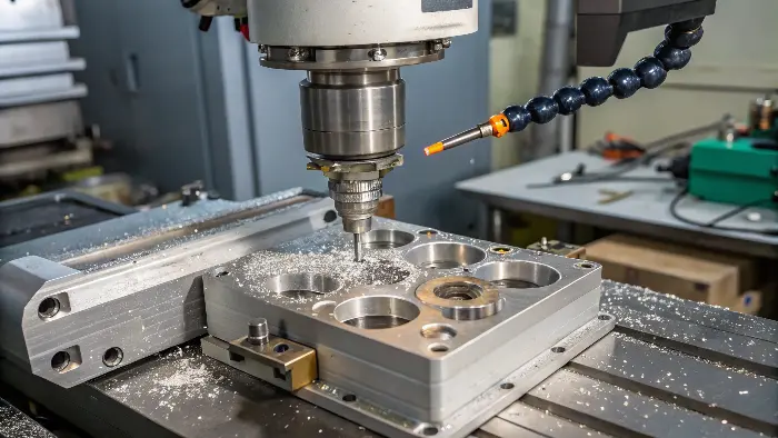
I often tell my clients, like Alex who designs intricate robotic components, that DFM isn’t about limiting creativity; it’s about channeling it effectively. It’s about thinking like a machinist while you’re still at the design screen.
-
The Core Principle of DFM
The fundamental idea is to anticipate and mitigate potential manufacturing problems during the design phase. This proactive approach contrasts with designing in a vacuum and then "throwing it over the wall" to manufacturing, hoping for the best. It’s a collaborative mindset, even if you’re the sole designer. -
Why DFM Matters for CNC Machining
CNC machining is versatile, but it has its constraints. Tool access, material removal rates, setup times, and tool wear all impact cost and speed. DFM helps you design parts that work with these constraints, not against them. For instance, avoiding deep, narrow pockets means standard tools can be used, reducing machining time. -
Key Goals of DFM in a CNC Context
The primary goals are to reduce cost, improve quality, and shorten lead times. This is achieved by simplifying designs, standardizing features, selecting appropriate materials, and specifying realistic tolerances. I once worked on a part where simply changing internal sharp corners to small radii (as all end mills are round) cut machining time by 15% because it eliminated the need for a secondary EDM process.
Here’s how DFM changes the game:
| Aspect | Traditional Approach | DFM Approach | Benefit |
|---|---|---|---|
| Design Focus | Primarily aesthetics/function | Function, aesthetics, and manufacturability | Reduced iterations, faster time-to-market |
| Cost Estimation | Often an afterthought, leading to surprises | Integrated into design, enabling cost control | Lower overall production cost, predictability |
| Lead Time | Prone to extensions due to unforeseen issues | Minimized through proactive problem-solving | Quicker, more reliable turnaround |
| Quality/Yield | Higher potential for defects or rework | Designed for higher yield and better consistency | Improved part quality, less material waste |
By embracing DFM, you’re not just designing a part; you’re designing a smoother, more efficient path to a finished product.
What is IPM in CNC Machining, and How Does DFM Influence It?
Problem: You need your parts machined quickly, but some designs seem to take forever on the machine. Agitation: Slow machining means higher costs and longer waits, potentially delaying your entire project. Solution: Understanding factors like IPM and how DFM impacts them can speed things up.
IPM in CNC machining stands for "Inches Per Minute." It’s a critical feed rate measurement indicating how fast the cutting tool moves through the material. Higher IPM generally means faster machining and lower costs, and DFM choices directly influence achievable IPM.
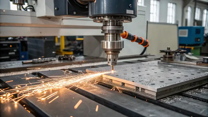
When I discuss machining strategies with engineers, IPM is a key factor. It’s not just about how fast the spindle spins (RPM), but how quickly we can actually cut material.
-
Defining IPM (Inches Per Minute)
IPM is calculated based on factors like spindle speed (RPM), the number of cutting edges (flutes) on the tool, and the chip load (the amount of material removed by each cutting edge per revolution). The formula is generally: IPM = RPM × Chip Load × Number of Flutes. It dictates the linear speed of the tool’s cutting path. -
How IPM Impacts Machining Time and Cost
A higher IPM means the tool completes its cutting paths more quickly. Since machine time is a major cost driver in CNC machining, faster cycle times directly translate to lower per-part costs. If a part can be machined at 60 IPM instead of 30 IPM, the cutting time for those operations is essentially halved. -
DFM Strategies to Optimize for IPM
Your design choices heavily influence the possible IPM. For example, designing parts with generous radii instead of sharp internal corners allows the machine to maintain a higher, more consistent feed rate. Thin walls or delicate features might require a lower IPM to prevent vibration or breakage. Selecting materials with good machinability also allows for higher IPM. I remember Alex had a design with very narrow slots; widening them slightly allowed us to use a more robust tool at a higher IPM, saving significant time.
Here are some factors influencing IPM and related DFM actions:
| Factor Influencing IPM | DFM Action to Optimize | Impact on Machining |
|---|---|---|
| Material Hardness | Select more machinable materials (e.g., Aluminum 6061 vs. Stainless Steel 316) if application allows. | Allows significantly higher IPM, reduces tool wear. |
| Tool Engagement | Design features to avoid full-slotting where possible; use trochoidal milling paths for deep pockets. | Reduces cutting forces, enables higher IPM. |
| Feature Complexity | Simplify features; avoid deep, narrow pockets or slots. | Allows use of larger, more rigid tools at higher IPM. |
| Part Rigidity | Ensure sufficient wall thickness; add ribs for support if needed. | Reduces vibration, permits higher, more stable IPM. |
Optimizing your design for a better IPM is a smart DFM move that pays off in faster production and lower costs.
What Does CNC MDI Stand For, and Is It Relevant to DFM?
Problem: You hear terms like "MDI mode" in CNC discussions, but you’re unsure what it means or if it affects your design process. Agitation: Not understanding machine operations can make it harder to communicate effectively with manufacturers. Solution: Knowing basic CNC modes like MDI helps you appreciate the manufacturing context.
MDI in CNC machining stands for "Manual Data Input." It’s a mode on CNC controllers that allows operators to manually enter and execute single blocks of G-code or M-code commands directly at the machine, without running a full program. While not a primary DFM driver, understanding MDI helps appreciate setup and quick adjustments.
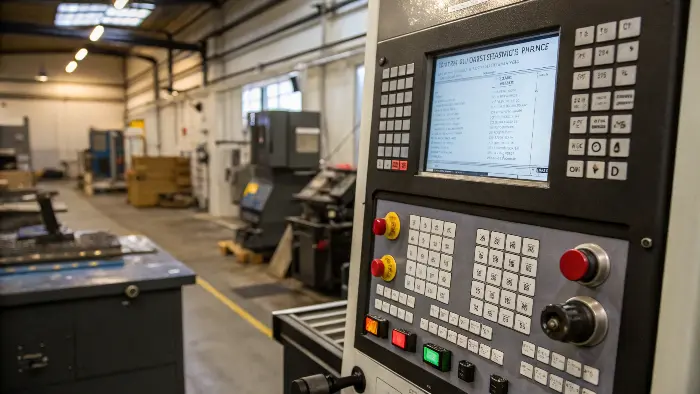
While DFM focuses on the part design itself, understanding how machines are operated, even for simple tasks, gives a fuller picture. MDI is one such operational aspect.
-
MDI Explained: Manual Data Input
Think of MDI as a command line for the CNC machine. The operator can type in a short instruction, like "G00 X10.0 Y5.0" (rapid move to X=10, Y=5) or "M03 S1500" (start spindle clockwise at 1500 RPM), and the machine executes it immediately. This is different from running a pre-written program stored in memory. -
When is MDI Used in CNC Machining?
MDI is typically used for simple, non-repetitive tasks. Common uses include:- Setups: Moving axes to specific positions for tool changes, workpiece loading, or setting work offsets (telling the machine where the part is located).
- Quick Operations: Drilling a single hole, facing a small surface, or making a simple cut without writing a full program.
- Testing: Executing a single line of code to test a tool or a movement.
- Minor Adjustments: Sometimes, an operator might use MDI to make a very minor adjustment if a program isn’t quite perfect, though this is less common for production runs.
-
MDI and DFM: Streamlining Setups and Quick Edits
While DFM primarily aims to optimize the main machining program, designs that are easier to set up can indirectly benefit. For example, if a part is designed to be fixtured simply, the MDI commands needed during setup might be fewer or less complex. Good DFM reduces the need for on-the-fly MDI adjustments to "fix" a program because the design is already optimized for the intended machining process. I’ve seen operators use MDI to quickly probe a feature on a first-off part to verify a dimension before starting a long production run – a good DFM design makes such checks straightforward.
Here’s a look at MDI use cases and their DFM relevance:
| MDI Use Case | Description | DFM Relevance |
|---|---|---|
| Setting Work Offsets (G54-G59) | Defining the origin point of the part on the machine table. | Designs with clear, accessible datums simplify this MDI process. |
| Tool Changes | Manually commanding a tool change (e.g., M06 T01). | DFM aims to minimize tool changes by standardizing features. |
| Simple Machining Tasks | Facing a block, drilling a test hole. | Often used for prototypes or first articles where DFM is being validated. |
| Program Verification | Stepping through initial program lines or testing specific movements. | A well-designed part (DFM) leads to a program that needs less MDI tweaking. |
Understanding MDI isn’t crucial for designing your part, but it helps appreciate the machinist’s workflow and how a well-thought-out design (thanks to DFM) can make their job, including setups using MDI, smoother.
Understanding Machining Tolerances: What Can You Expect, and How Does DFM Help?
Problem: You need precise parts, but specifying tight tolerances everywhere dramatically increases costs. Agitation: This can make your project unfeasible or force you to compromise on quality elsewhere. Solution: Understand standard tolerances and apply tight ones only where DFM principles show they are critical.
Standard CNC machining tolerances are typically around ±0.005 inches (±0.127mm), though this varies. DFM helps by guiding you to apply tighter tolerances only to critical features, using standard tolerances elsewhere to manage cost and manufacturability effectively. For example, Protolabs often states a general tolerance like this for many of their processes.
Tolerance is a constant topic of discussion with engineers like Alex, who needs high precision for his robotic systems. The key is strategic tolerancing, guided by DFM.
-
General Machining Tolerances: A Baseline
Most CNC shops can achieve a general tolerance of ±0.005 inches (±0.127mm) or ±0.002 inches (±0.05mm) without extraordinary effort or cost for many metals. Plastics might have slightly looser standard tolerances due to their nature. Companies like Protolabs often publish their typical achievable tolerances, which serve as a good general guide. For instance, they might state ±0.1 mm as a standard for many features. It’s always best to confirm with your specific supplier, as capabilities vary. -
How DFM Influences Achievable Tolerances
DFM plays a huge role here.- Feature Design: Simple, robust features are easier to machine to tight tolerances than complex, delicate ones. For example, a hole on a flat, well-supported surface is easier to hold to a tight tolerance than one on a thin, angled wall.
- Material Selection: Stable materials like Aluminum 6061 or tool steels hold tolerances better than materials prone to warping or flexing during machining.
- Overall Part Complexity: The more features and operations, the greater the chance of tolerance stack-up. DFM encourages simplifying the overall design.
- Surface Finish: Tighter tolerances often go hand-in-hand with finer surface finishes, which can add machining time and cost. DFM asks if that ultra-fine finish is truly needed everywhere.
-
Communicating Tolerances Effectively
Clearly indicate on your drawings which tolerances are critical and which can be standard. Use geometric dimensioning and tolerancing (GD&T) for complex relationships. I always advise clients to avoid a "blanket tolerance" in the title block that applies to everything. Instead, specify general tolerances and then call out tighter ones only on specific dimensions.
Here’s a general guide to tolerance levels and DFM considerations:
| Tolerance Level | Typical Range (+/- mm) | DFM Considerations | Cost Impact |
|---|---|---|---|
| Standard/General | 0.1 to 0.25 | Default for non-critical features. Design for this unless a tighter fit is essential. | Low |
| Medium | 0.05 to 0.1 | For mating parts or features needing good alignment. Justify the need. | Medium |
| Tight/Precision | 0.01 to 0.05 | Only for critical functional features (e.g., bearing bores, press fits). Simplify surrounding geometry. | High |
| Very Tight | < 0.01 | Requires specialized machining, grinding, lapping, and controlled environments. Design for inspectability. | Very High |
When Alex needed a ±0.01mm tolerance for a shaft fit, we ensured the DFM for that feature was perfect – good material access, robust support, and a simple cylindrical form. Other non-critical areas of the same part used a ±0.1mm tolerance, balancing precision with cost.
Conclusion
Embracing DFM for CNC machining, understanding terms like IPM and MDI, and strategically applying tolerances are not just buzzwords. They are practical approaches that I’ve seen save my clients significant time and money, leading to better, more efficiently produced parts.
