Are you ever puzzled by the huge variety of cutting tools available for CNC machining? Choosing the wrong one can lead to poor surface finish, broken tools, or even damaged workpieces. This uncertainty can slow down your projects and increase costs.
A CNC machinist selects the right tool by carefully considering the workpiece material, the specific machining operation (like roughing or finishing), the part’s geometry, and the capabilities of the CNC machine itself. Experience and good technical data are key to making the best choice for quality and efficiency.

Choosing the right cutting tool is a really important skill in CNC machining. It’s something I’ve learned over many years, often through trial and error in the early days. It’s not just about picking a tool that looks right; it’s about understanding how different factors work together. For engineers like Alex, getting this right means their high-tolerance parts come out perfectly. Let’s explore what goes into this critical decision-making process.
How do you choose the appropriate cutting tool for a CNC lathe operation?
Are you struggling to get the perfect finish or optimal cutting speeds on your lathe projects? Using a less-than-ideal tool can result in chatter, rapid tool wear, or parts that don’t meet specifications. This can be frustrating and costly.
To choose the right cutting tool for a CNC lathe, you need to look at the material being turned, the type of operation (e.g., facing, turning, grooving, threading), the required surface finish, and the rigidity of your setup. Each of these factors will guide your choice of tool material, geometry, and coating.
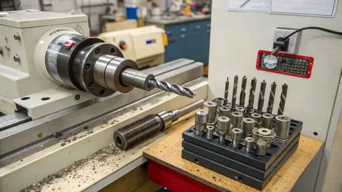
CNC lathes are amazing for making round parts, but the tool choice is critical. I remember a project for Alex involving some complex stainless steel shafts. The initial tool we tried wore out too quickly and left a poor finish. We had to rethink our tool selection carefully.
My insight about considering material type, geometry, finishing requirements, and workholding is especially true here.
For lathe operations, we look at several things:
- Workpiece Material: Is it a soft material like aluminum, or a tough one like stainless steel or Inconel? This dictates the tool material (e.g., High-Speed Steel (HSS), carbide, ceramic, or CBN/PCD) and its coating. For instance, for hardened steels, a CBN (Cubic Boron Nitride) insert might be best.
- Operation Type:
- Roughing: Needs a strong tool that can remove a lot of material quickly. The surface finish isn’t the main concern here.
- Finishing: Needs a tool with a specific nose radius and geometry to achieve a smooth surface.
- Grooving/Parting: Requires tools with specific widths and shapes.
- Threading: Needs specialized threading inserts matching the thread profile.
- Tool Geometry: This includes the rake angle, clearance angle, and nose radius. The chipbreaker design is also vital for controlling chips, which is very important in lathe work to prevent them from wrapping around the part or tool.
- Workholding and Machine Rigidity: If the part is long and slender or the machine isn’t very rigid, you might choose a tool that exerts less cutting force to avoid vibration.
We often use indexable inserts on lathes. This means we can quickly change a worn cutting edge without removing the whole tool holder. Choosing the right insert grade and chipbreaker for the job is a science in itself.
What are the criteria for CNC machine selection that influence tooling?
Are you finding that your machine’s limitations are dictating your tool choices, rather than the job’s requirements? An underpowered or less rigid machine might force you to use tools or cutting parameters that are not ideal, leading to longer cycle times or compromised quality.
When selecting tools, a machinist must consider the CNC machine’s specifications. Key criteria include its spindle horsepower and torque, maximum spindle speed, the type of tool holding system (e.g., CAT40, HSK63), and the capacity of the automatic tool changer (ATC). These factors directly impact which tools can be used effectively.
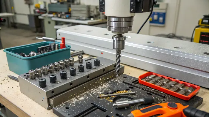
The machine itself plays a huge role in what tools you can effectively use. It’s not just about whether a tool fits; it’s about whether the machine can drive it properly. I’ve seen situations where a perfectly good tool underperforms simply because the machine wasn’t up to the task.
Here’s how machine characteristics affect tool selection:
- Spindle Power and Torque: A machine with high horsepower and torque can handle larger diameter tools and more aggressive cuts (deeper depth of cut, higher feed rates). If you try to use a large tool on a low-power machine, you might stall the spindle or get poor results. For example, a large face mill for roughing a big aluminum plate needs a machine with plenty of power.
- Spindle Speed (RPM): Some materials, especially aluminum, benefit from high cutting speeds. If your machine has a high-speed spindle, you can use tools designed for these speeds, often smaller diameter tools, to achieve better finishes and faster material removal. Conversely, for tough materials, you might need lower RPM but higher torque.
- Tool Holder System: The type of tool holder interface (like BT, SK, CAT, HSK) affects rigidity and balance at high speeds. HSK holders, for instance, are often preferred for high-speed machining due to their superior clamping force and balance. The size of the taper (e.g., 30, 40, 50) also determines how large and robust a tool can be supported.
- Automatic Tool Changer (ATC) Capacity: If a job requires many different tools, a machine with a large ATC capacity is beneficial. This avoids manual tool changes, saving time. The ATC also has limits on tool weight and diameter.
Thinking about Alex’s precision robotics parts, he often needs fine details. This might mean using small-diameter tools at high RPMs. The machine must be capable of this, with a well-balanced spindle and precise motion control.
What factors should be considered when selecting a program for a CNC machine that impacts tool choice?
Are your CNC programs forcing you to make compromises in tool selection, or vice-versa? A program written without considering optimal tooling can lead to inefficient machining, or you might choose tools that aren’t ideal just to fit an existing program.
When selecting or creating a CNC program, factors that heavily influence tool choice include the types of operations (e.g., pocketing, contouring, drilling, tapping), the depth and width of cuts, the required tolerances and surface finishes, and the overall machining strategy (e.g., high-speed machining, heavy roughing). The program essentially dictates the tool’s path and engagement.
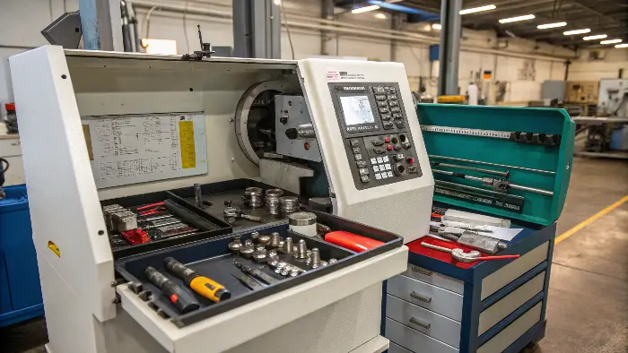
The CNC program is the set of instructions that tells the machine what to do. Naturally, this has a massive impact on the tools we select. I always think of the program and the tooling as two sides of the same coin; they have to work together.
Here’s how programming considerations guide tool selection:
- Types of Operations:
- Roughing: The program will aim to remove material quickly. This usually means selecting robust tools like large-diameter end mills or face mills that can handle heavy chip loads.
- Finishing: The program will focus on achieving the final dimensions and surface quality. This often requires tools with specific geometries, like ball-nose end mills for 3D contours or end mills with corner radii for smooth transitions.
- Holemaking: Drilling, reaming, boring, and tapping all require specific tools. The program will define hole diameters, depths, and thread pitches, directly leading to tool selection. For example, if Alex needs a precise M6 threaded hole, the program will call for a specific tap drill and then an M6 tap.
- Feature Geometry: Deep pockets might need long-reach end mills. Narrow slots require small-diameter tools. Complex 3D surfaces often benefit from ball-nose or lollipop cutters.
- Machining Strategy: A program using High-Speed Machining (HSM) toolpaths, which often involve shallow radial depths of cut but high feed rates and spindle speeds, will require tools designed for HSM. These tools often have more flutes and specific coatings.
- Tool Library and Availability: Practically, the program might be written considering the tools already available in the shop’s library to save on costs and setup time.
I always advise my clients that good CAM programming is essential. A skilled programmer can create toolpaths that not only make the part correctly but also optimize tool life and reduce machining time. This often involves selecting the right tool for each specific segment of the program.
How does a machinist measure tools for tool length offsets?
Are you experiencing inaccuracies in your machined parts, like features not being at the correct depth? This could be due to incorrect tool length offsets. If the machine doesn’t know the exact length of the tool, it can’t position it accurately.
A machinist measures tools for tool length offsets by determining the precise distance from the tool’s cutting tip to a reference point on the machine’s spindle (often called the gauge line). This is done using a tool pre-setter, a touch probe, or by carefully "touching off" the tool on a known surface.
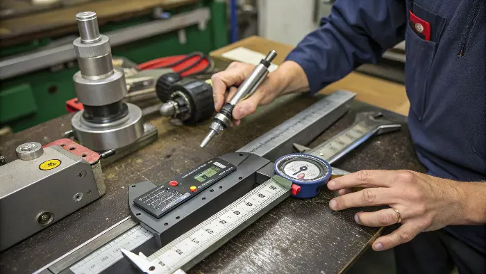
Once you’ve selected the perfect tool, there’s another crucial step: telling the machine exactly how long that tool is. This is called setting the tool length offset. Without this, even the best tool won’t cut accurately. I’ve seen jobs go wrong because of a simple mistake in this measurement.
Here’s a breakdown of the process and its importance:
- Why it’s Important: The CNC machine needs to know the exact Z-axis position of the tool’s cutting edge relative to the workpiece. The tool length offset value compensates for the varying lengths of different tools. If this value is wrong, holes will be too deep or too shallow, and surfaces won’t be where they’re supposed to be. This is critical for Alex’s high-tolerance parts.
- Methods of Measurement:
- Tool Pre-setter: This is an offline device that measures the tool’s length (and sometimes diameter) very accurately. The measured value is then input into the machine’s controller. This is the most efficient method for shops with many tools.
- On-Machine Probe: Many modern machines have a touch probe. The tool is loaded into the spindle, and the machine automatically touches the tool tip to the probe to measure its length.
- Manual Touch-Off: The machinist carefully brings the tool down to touch a known surface, like the top of the workpiece (if its Z-height is known) or a precision gauge block on the machine table. The machine’s Z-axis position is then recorded as the offset. This requires skill and care.
- Storing the Offset: The measured length is stored in the machine’s tool offset registry, associated with a specific tool number (e.g., T01, T02). When the program calls for that tool, the machine uses the stored offset value.
I always stress to my team that double-checking tool length offsets is vital. A small error here can lead to scrapped parts, which costs time and money. It’s a fundamental part of setting up any CNC job correctly.
Conclusion
Selecting the right CNC tool involves understanding the material, the operation, the part’s design, and your machine’s capabilities. Then, accurately measuring and setting that tool is key. These steps ensure precision, efficiency, and high-quality results in every CNC machining project, helping bring complex designs to life.
