Designing parts for CNC machining can feel like a balancing act. You need functionality and precision, but complex designs often lead to high costs and long lead times. It’s frustrating when your innovative ideas get stuck in manufacturing, right?
Yes, by following established Design for Manufacturability (DFM) guidelines, you can significantly streamline the CNC machining process. These guidelines help you create parts that are easier, faster, and more economical to produce, ensuring your projects stay on track and within budget. I’ve seen these principles make a huge difference for engineers worldwide.
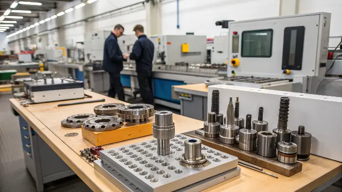
I’ve spent years in the CNC machining world, from working hands-on in a shop to now helping engineers like Alex from Germany get their custom parts made efficiently. DFM isn’t just a theory; it’s a practical approach that delivers real results. Let’s explore these guidelines to help you optimize your designs. You’ll want to see how these can simplify your next project.
What is DFM in Machining, and Why is it a Game-Changer?
Problem: You’ve poured hours into a design, only to find out it’s incredibly expensive or difficult to machine. Agitation: This often means going back to the drawing board, causing delays and budget stress. Solution: Understanding DFM from the start can prevent these costly revisions.
DFM, or Design for Manufacturability, in machining is the process of intentionally designing parts to be as easy and cost-effective to produce as possible using CNC methods. It involves considering manufacturing constraints and capabilities early in the design phase, leading to smoother production and lower costs.

I always emphasize to my clients that DFM isn’t about stifling innovation. It’s about smart design. Think of it as designing with the machinist looking over your shoulder, offering helpful advice.
-
The Core Idea of DFM
At its heart, DFM is about foresight. It’s about anticipating potential manufacturing challenges while you’re still designing and making choices that avoid those problems. This proactive approach is far more efficient than fixing issues after the design is supposedly "complete." It means thinking about how each feature will actually be cut, what tools will be used, and how the part will be held. -
Why DFM is Crucial for CNC
CNC machining is incredibly versatile, but it’s not magic. Tools have sizes and shapes, machines have limitations, and materials behave differently. DFM helps align your design with these realities. For example, designing internal corners with a radius (because cutting tools are round) instead of sharp 90-degree angles can save an entire manufacturing step, like EDM, which adds significant cost and time. -
Key Benefits of Implementing DFM
The advantages are clear: reduced costs, faster turnaround times, and improved part quality. By simplifying features, standardizing components, choosing appropriate materials, and specifying realistic tolerances, you make the machinist’s job easier, which directly benefits your project. I remember a client who initially had a very complex part; by applying DFM principles, we reduced its machining time by 30% without compromising its function.
Here’s a quick comparison:
| Aspect | Traditional Design Focus | DFM-Oriented Focus | Primary Benefit for You |
|---|---|---|---|
| Feature Design | Aesthetics, then function | Manufacturability, then function/aesthetics | Lower machining costs, faster production |
| Tolerances | Often overly tight "just in case" | Applied only where functionally critical | Reduced scrap rate, lower inspection costs |
| Material Choice | Based purely on ideal properties | Properties balanced with machinability | Better cycle times, less tool wear |
Embracing DFM means you’re not just designing a part; you’re designing an efficient manufacturing process for it.
What are the Key Rules of Thumb for CNC Machining You Should Always Follow?
Problem: You want your CNC machined parts to be perfect, but sometimes small design oversights lead to big production issues. Agitation: This can result in parts that are weak, difficult to make, or unnecessarily expensive. Solution: Following some basic DFM rules of thumb can prevent these common pitfalls.
Key rules of thumb for CNC machining include maintaining adequate wall thickness, using generous internal radii instead of sharp corners, designing standard-sized holes with appropriate depths, and simplifying features wherever possible. Adhering to these guidelines makes parts more robust, easier to machine, and more cost-effective.
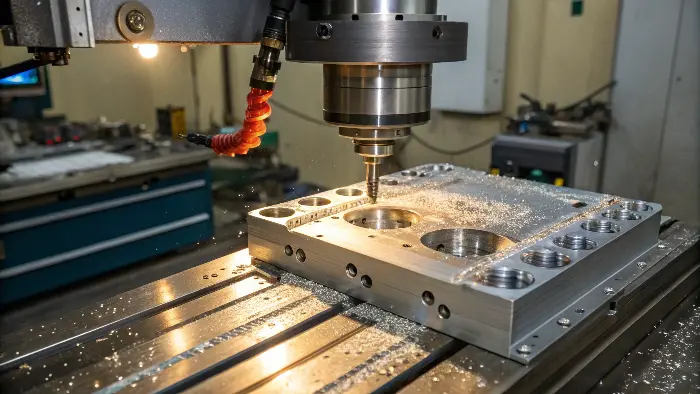
These aren’t strict laws, but they are strong recommendations based on years of machining experience. I’ve seen Alex, my engineer client, refine his designs using these rules to great effect.
-
Wall Thickness and Ribs
Thin walls are prone to vibration and distortion during machining, and can even break.- Guideline: For metals, aim for a minimum wall thickness of 0.03 inches (0.8mm), and for plastics, 0.06 inches (1.5mm). If thin walls are unavoidable, consider adding ribs for support. This was a lesson learned on a housing Alex designed; slightly thicker walls dramatically improved its stability during machining.
-
Internal Radii (No Sharp Corners!)
CNC cutting tools are round, so they naturally create internal radii. Trying to machine a perfectly sharp internal corner is often impossible or requires very slow, specialized processes like EDM.- Guideline: Design internal corners with a radius that is at least 1/3 of the cavity depth, and ideally larger than the radius of the cutting tool you anticipate being used. A 3mm radius is much easier and faster to machine than a 0.5mm radius.
-
Hole Design
- Guideline (Standard Sizes): Use standard drill sizes whenever possible. Custom hole sizes require extra operations like reaming or boring, adding cost.
- Guideline (Depth): For through-holes, depth isn’t usually an issue. For blind holes, try to limit depth to 4-6 times the hole diameter. For tapped blind holes, ensure sufficient thread depth (typically 1.5x bolt diameter) and add extra clearance at the bottom for the tap and chips.
-
Feature Simplification
- Guideline: Avoid unnecessarily complex geometries, deep pockets, or tiny features if simpler alternatives would function just as well. Every complex curve or intricate detail adds machining time.
Here’s a table summarizing some common rules:
| DFM Rule of Thumb | Problematic Design Example | Recommended DFM Approach | Benefit |
|---|---|---|---|
| Wall Thickness (Metal) | 0.3mm wall | >0.8mm wall, or add ribs | Reduced vibration, better part integrity |
| Internal Corners | Sharp 90-degree internal corner | Radius > 1mm (ideally >3mm) | Machinable with standard tools, faster |
| Hole Diameter | Custom 5.37mm diameter | Standard 5.0mm or 5.5mm diameter | No need for custom tooling/reaming |
| Deep Pockets | Pocket depth > 6x width | Pocket depth < 4x width, or use wider pocket | Better tool access, improved chip evacuation |
Following these simple rules can make a massive difference in the manufacturability and cost of your parts.
What are the Standard Tolerances for CNC Machining, and How Tight Should You Go?
Problem: You need precise parts, so you specify very tight tolerances on all dimensions. Agitation: This can drastically increase machining time, inspection costs, and the likelihood of rejected parts, blowing your budget. Solution: Understand standard tolerances and apply tight ones judiciously.
Standard CNC machining tolerances are typically around ±0.005 inches (±0.127mm) for general features, though this can vary by material and shop capability. Tighter tolerances, like ±0.001 inches (±0.025mm) or less, are achievable but should only be specified for critical functional features due to increased cost.
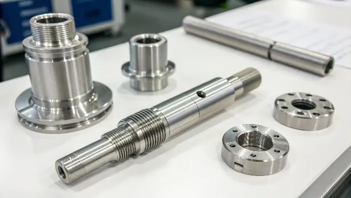
This is a frequent topic with engineers like Alex, who often works with high-precision components for robotics. The key is to be precise where it matters.
-
Understanding General Tolerances
Most CNC shops can comfortably hold a general tolerance of ±0.005" (or about ±0.1mm) for many dimensions without special effort. This is often the default if no specific tolerance is called out. Some shops, like Protolabs, might state a general tolerance of ±0.1mm for many of their standard processes. Always clarify with your supplier, as capabilities differ. -
When to Specify Tighter Tolerances
Tighter tolerances are necessary for features like:- Bearing fits or press fits
- Mating surfaces that require precise alignment
- Features critical to the part’s specific function where small variations matter.
For all other non-critical features, a standard tolerance is usually sufficient and much more economical. I always ask, "What is the functional impact if this dimension is off by an extra 0.05mm?"
-
Cost Implications of Tolerances
The tighter the tolerance, the higher the cost. This is because achieving tighter tolerances may require:- Slower machining speeds and feeds
- More precise (and expensive) tooling
- Additional finishing operations (e.g., grinding)
- More rigorous and time-consuming inspection methods
- Higher scrap rates
-
Communicating Tolerances Effectively
Use clear callouts on your drawings. Specify a general tolerance in the title block, and then explicitly note tighter tolerances only on the dimensions that truly require them. Geometric Dimensioning and Tolerancing (GD&T) is essential for complex parts to define functional relationships.
Here’s a general idea of tolerance impact:
| Tolerance Level | Typical Range (+/- inches) | Typical Range (+/- mm) | Relative Cost Impact | DFM Consideration |
|---|---|---|---|---|
| Standard/General | ±0.005" to ±0.010" | ±0.127 to ±0.254 | Low | Default for non-critical features. |
| Medium | ±0.002" to ±0.004" | ±0.050 to ±0.100 | Medium | For good fits, alignment. Justify the need. |
| Tight/Precision | ±0.0005" to ±0.001" | ±0.013 to ±0.025 | High | Critical features only. Design for inspectability. |
| Very Tight | < ±0.0005" | < ±0.013 | Very High | Requires specialized processes, e.g., grinding. |
I worked with a client who had specified ±0.001" on almost every dimension of a large plate. After reviewing the function, we found only two hole patterns needed that precision. Changing the rest to ±0.005" cut the part cost by nearly 40%.
How Do You Select the Right Machining Parameters for Aluminium on a CNC Machine?
Problem: You’re designing an aluminum part, but you’re unsure how material properties affect machining, potentially leading to poor surface finish or slow production. Agitation: Incorrect parameters mean wasted time, material, and money. Solution: Understanding key parameters for aluminum helps optimize the process.
Selecting parameters for machining aluminum involves balancing spindle speed (RPM), feed rate (IPM or MMPM), and depth of cut. For aluminum, high speeds and feeds are generally preferred, along with sharp tooling (often 2-3 flutes) and adequate coolant to prevent material buildup on the tool.
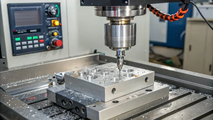
Aluminum is a popular choice for CNC machining due to its excellent machinability, but "dialing in" the parameters is key. I often advise clients on this, especially when they are prototyping.
-
Key Parameters: Speed, Feed, Depth of Cut
- Spindle Speed (RPM): Aluminum alloys generally allow for high spindle speeds. This helps in achieving a good surface finish and efficient material removal.
- Feed Rate (IPM/MMPM): This is how fast the tool moves through the material. Higher feed rates are possible with aluminum, but must be balanced with the desired surface finish and tool life.
- Depth of Cut (DOC): This is how much material the tool removes in one pass. A deeper DOC can reduce the number of passes but increases cutting forces. For finishing passes, a lighter DOC is used.
-
Influence of Aluminum Grade
Different aluminum alloys have different machining characteristics.- 6061-T6: Very common, excellent machinability, good for general-purpose parts. Allows aggressive parameters.
- 7075-T6: Stronger than 6061, but can be more "gummy" and abrasive. May require slightly adjusted speeds/feeds and very sharp tools to prevent built-up edge (BUE).
- MIC-6: A cast tooling plate, very stable and machines beautifully, often used for flat, precise components.
-
Tooling Considerations for Aluminum
- Material: High-Speed Steel (HSS) can work, but Carbide tools are generally preferred for better tool life and performance at high speeds.
- Flutes: 2 or 3-flute end mills are common for aluminum. They provide good chip evacuation, which is crucial as aluminum produces large, soft chips.
- Coatings: Uncoated, highly polished carbide tools or tools with specific coatings (like TiB2 or DLC) designed for aluminum can prevent material from sticking to the cutting edge.
-
Coolant Usage
Flood coolant or mist coolant is highly recommended when machining aluminum. It helps to:- Reduce heat at the cutting zone.
- Prevent aluminum from welding to the tool (BUE).
- Flush chips away from the cutting area.
Here’s a table for general guidance:
| Parameter/Aspect | Consideration for Aluminum Machining | Expected Outcome/Benefit |
|---|---|---|
| Spindle Speed (RPM) | High (e.g., 5,000 – 20,000+ RPM depending on machine/tool) | Better surface finish, efficient cutting |
| Feed Rate (IPM) | Relatively high, balanced with chip load | Faster cycle times |
| Tooling | Sharp carbide, 2-3 flutes, polished or specific coating (e.g., ZrN, TiB2) | Reduced BUE, good chip evacuation, longer tool life |
| Coolant | Essential (flood or mist) | Prevents BUE, cools tool & workpiece, aids chip removal |
| Depth of Cut (DOC) | Aggressive for roughing, light for finishing | Efficient material removal, good final surface finish |
For instance, when machining a 6061 aluminum enclosure for Alex, we used high RPMs, a moderate feed rate with a 3-flute coated carbide end mill, and flood coolant. This resulted in a great surface finish and quick cycle times.
Conclusion
Applying these DFM guidelines—understanding DFM’s core, using rules of thumb, managing tolerances wisely, and selecting appropriate machining parameters—will significantly enhance your CNC projects. This leads to more efficient production, lower costs, and higher quality parts, making your designs a manufacturing success.
