Aircraft safety is paramount. Tiny part errors can be catastrophic. Let’s explore essential manufacturing precision for these flying machines.
Critical tolerances for aircraft structural components are extremely tight, often in micrometers. These define acceptable deviations from design specifications. This ensures structural integrity, flight safety, and part interchangeability, especially for load-bearing elements.
When I first started in CNC machining over a decade ago, the sheer precision demanded by aerospace clients was an eye-opener. It’s not just about making a part that fits. It’s about making a part that performs flawlessly under extreme conditions, flight after flight. We often talk about tolerances in manufacturing. But what do they truly mean in the context of an aircraft, where human lives are directly at stake? This topic can seem complex. But it is very important to understand. This is true if you make or design these amazing machines. Let’s look at it more closely.
What are the critical parts of an aircraft?
Aircraft are complex machines. Some part failures are minor, others catastrophic. Knowing critical components is vital for focusing our precision.
Critical aircraft parts include wings, fuselage sections, landing gear, engine mounts, and flight control surfaces. These components bear significant loads and stresses during flight. Their failure could lead to loss of control or structural integrity.
When we talk about "critical parts," we’re really discussing components where failure is simply not an option. Think about the immense forces at play during takeoff, throughout the flight, and during landing. I’ve seen designs for wing spars, for example. The material specifications and the required tolerances for these parts are incredibly demanding. These spars are the backbone of the wing. They must handle bending moments and shear forces that are truly enormous.
Then you have the fuselage. It isn’t just a metal tube to hold passengers or cargo. It’s a pressurized vessel at high altitudes. It also contributes significantly to the overall structural rigidity of the aircraft.
Engine mounts are another classic example of critical parts. They have to hold incredibly powerful engines securely to the airframe. They must also absorb vibrations and withstand extreme temperature changes.
And let’s not forget the landing gear. It takes the full impact of the aircraft’s weight during every landing, repeatedly. Even smaller components within flight control systems, like actuators or linkages, are absolutely critical. If a pilot cannot control the ailerons or rudder with complete precision, the consequences are immediate and severe. So, the definition of "critical" is directly tied to flight safety and the ability of the aircraft to perform its intended function reliably. At QuickCNCs, we machine these parts with the utmost care because every detail matters for flight integrity.
What is the difference between primary and secondary aircraft structures?
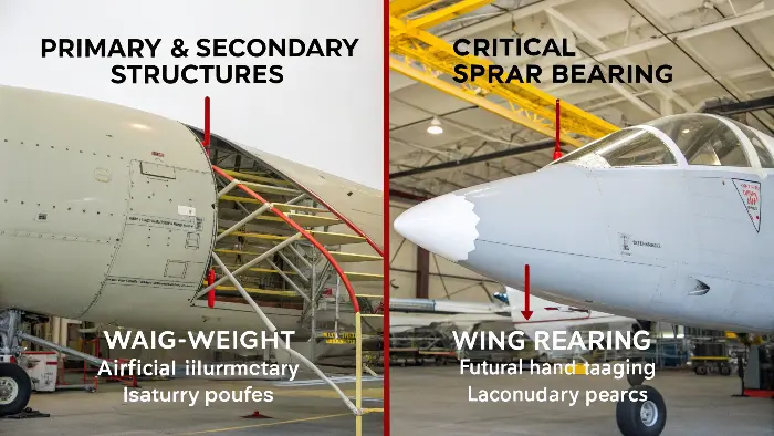
| Aircraft structures look solid. But different parts have different jobs and levels of importance. Knowing this difference is crucial for design, manufacturing, and maintenance. Primary structures are critical load-bearing components like wing spars and fuselage frames. Their failure would be catastrophic. Secondary structures, like fairings or some interior panels, are not essential for flight safety, though they add to function.  This distinction between primary and secondary structures is vital in aerospace engineering and manufacturing. When I handle a blueprint for a primary structural component, I know the precision required and the level of inspection will be at the absolute highest level. These components, such as wing spars, main fuselage frames, or landing gear assemblies, carry the primary flight loads. Their failure is simply unthinkable. Secondary structures, on the other hand, like aerodynamic fairings, non-structural access panels, or many interior fittings, are still important. They contribute to aerodynamic efficiency, protect other components, or provide functionality. However, they are not essential for keeping the plane safely in the air. The design allowables, material choices, inspection criteria, and, very importantly, the manufacturing tolerances differ greatly between these two categories. For instance, primary structures demand extremely tight machining tolerances. Any deviation can compromise their load-bearing capacity or fatigue life. Secondary structures might have more lenient tolerances, focusing more on fit and function. Understanding this helps us at QuickCNCs prioritize our efforts and apply the correct level of rigor in our CNC machining processes. Here’s a quick comparison: |
Category | Primary Structures | Secondary Structures |
|---|---|---|---|
| Function | Carries major flight loads, essential for safety | Aerodynamic, protective, or non-load bearing | |
| Failure Consequence | Catastrophic loss of aircraft | Degraded performance, no immediate safety risk | |
| Key Examples | Wing spars, fuselage bulkheads, landing gear struts, engine pylons | Fairings, wingtips (some designs), non-structural doors, cabin fixtures | |
| Tolerance Focus | Absolute highest precision, minimal deviation allowed | Functional fit, less stringent on minor variations | |
| Material Integrity | Critical, any flaw meticulously inspected, full traceability | Important for function, but less critical than primary structures |
This clear separation ensures that safety is paramount. It also allows for efficiency in both the manufacturing process and ongoing maintenance of the aircraft. We treat every primary structural part with the focused attention and precision it absolutely deserves.
What are the structural limitations of aircraft?
Aircraft perform amazing feats of engineering. But all materials and designs have limits. Understanding these limits is essential to prevent catastrophic failures and ensure safe operation.
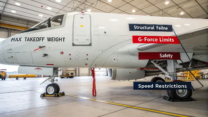
Aircraft structural limitations are set by material strength, fatigue life, and aerodynamic loads. These include max takeoff weight, G-force limits, and speed restrictions. Exceeding them risks structural failure and compromises safety.

Aircraft must operate within strict structural boundaries. These limits are not arbitrary. They are carefully defined by the materials used and the engineering design. In my experience helping clients source parts, I’ve seen how engineers constantly strive for components that are both incredibly lightweight and possess immense strength. This balance is critical for performance and efficiency, but safety is always the first priority. The manufacturing tolerances we achieve play a direct role in ensuring the aircraft can operate up to, but not beyond, these limitations.
Load Capacity (G-Limits)
Aircraft structures are designed to withstand specific G-forces (gravitational force equivalents). For example, a commercial airliner might be certified for a range like +2.5g (when pulling up) to -1g (when pushing down). Aerobatic planes can handle much higher Gs. Exceeding these design G-limits imposes stresses beyond the material’s capability. This can lead to permanent deformation or even structural failure. Precise parts ensure the structure behaves as predicted under such dynamic loads. Our machining helps guarantee this reliable performance.
Material Endurance (Fatigue Life)
Metals, especially common aircraft aluminum alloys, can weaken over many cycles of stress. This is called metal fatigue. Each cycle – like a takeoff, encountering turbulence, and landing – adds a tiny amount of "damage." Over thousands of flights, this damage accumulates. Critical parts have a calculated "fatigue life." They must be inspected or replaced before reaching this lifespan to prevent fatigue-induced cracks. Good machining, which creates smooth surfaces and accurate forms, reduces stress risers. This directly improves the part’s fatigue endurance.
Environmental & Aerodynamic Stresses
Aircraft components face extreme temperature variations. This ranges from icy conditions at high altitudes to high heat near engines or from aerodynamic friction. High-speed flight also imposes significant aerodynamic pressures and forces on the structure. Parts must maintain their strength and integrity across all these demanding operational conditions. The manufacturing process, including the precision of CNC machining, must preserve the material qualities specified by designers for these tough environments. This ensures the aircraft remains safe throughout its operational envelope.
What is the damage tolerance of aircraft structures?
Aircraft can get damaged during manufacturing, operation, or maintenance. Small flaws might grow if not found. Damage tolerance design is a philosophy that helps keep planes safe even with some damage.
Damage tolerance is an aircraft design philosophy. It ensures that if a structure gets damage (like cracks or corrosion) between inspections, it will not grow to a critical size. This prevents catastrophic failure before detection and repair.

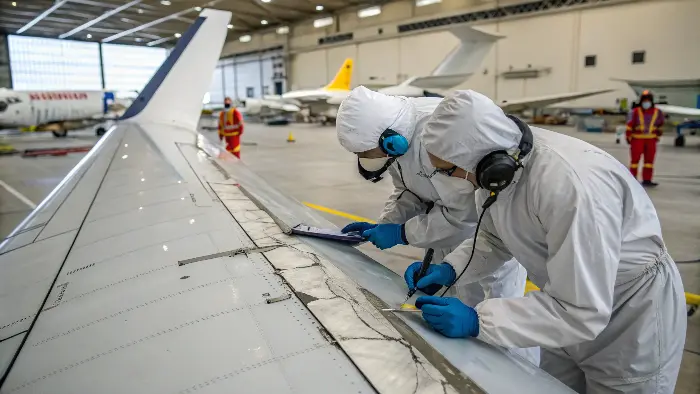
Damage tolerance is a key safety philosophy in modern aircraft design. It is a practical approach. It accepts that tiny flaws or imperfections might exist from the manufacturing process. It also accepts that parts can develop damage (like small cracks, corrosion, or impact damage) while in service. The main goal of damage tolerance design is to ensure that if such damage occurs, it will not grow to a critical size and cause a catastrophic failure of the structure between scheduled maintenance inspections. It’s about designing aircraft structures for resilience and inspectability. I’ve seen how this philosophy influences material choices, how parts are shaped, and the inspection methods used.
Predicting Flaw Behavior
To implement damage tolerance, engineers use a science called fracture mechanics. This science helps predict how fast a known or assumed small crack might grow when subjected to the typical stresses of flight operations. By understanding these crack growth rates, engineers can determine safe operational limits for a part even if it contains a small, acceptable flaw. This analysis is fundamental to setting safe inspection intervals.
Setting Inspection Intervals
Based on the predicted crack growth rates and the detectability of flaws, specific inspection intervals are established for critical components. These schedules ensure that any damage that might have initiated or grown is found and repaired long before it can compromise the overall integrity of the structure. Our role in precision machining is crucial here. We ensure that the initial quality of the parts means any inherent flaw sizes are well below the minimum assumptions made in the damage tolerance analyses.
Material and Design Choices for Resilience
Materials with high fracture toughness are preferred for damage-tolerant designs. Fracture toughness is a material’s ability to resist the propagation of a crack. Design features also play a role. These might include elements like crack-stopper holes (to arrest a growing crack) or redundant load paths. Redundant load paths mean if one structural element fails, another nearby element can safely take over the load. This provides an extra layer of safety.
Conclusion
Precision in aircraft parts isn’t just a goal; it’s a life-critical necessity. Understanding critical tolerances and design philosophies like damage tolerance ensures safer skies for everyone.
