Electronics overheating or misfitting in their cases? Poor tolerances can lead to system failures and assembly headaches. Precision is key for reliable performance.
For electronics enclosures, precise tolerances ensure proper fit, sealing (IP rating), and EMI shielding. For heatsinks, tight contact surface tolerances (flatness, roughness) are vital for effective thermal dissipation.
I’ve seen many projects, especially for clients like Alex developing sophisticated systems, where the enclosures and heatsinks are as critical as the electronics inside. The right tolerances aren’t just about looking good; they’re about functioning perfectly. At QuickCNCs, we handle these challenges daily. Let’s delve into why precision here is non-negotiable, drawing from my hands-on experience in global manufacturing.
Why Are Tight Tolerances Crucial for Electronics Enclosures?
Enclosure parts not aligning? Worried about dust or moisture ingress? Loose tolerances in enclosures can compromise sensitive electronics. Precision fit is essential for protection.
Tight tolerances in electronics enclosures guarantee component alignment, secure sealing against environmental factors (dust, water), effective EMI/RFI shielding, and overall structural integrity for protection.
When we machine enclosures, several tolerance aspects become critical. I remember a client, much like Alex, who was working on a ruggedized outdoor sensor unit. The enclosure absolutely needed to be perfectly sealed to protect the sensitive electronics from harsh weather. If the tolerances weren’t spot on, the device would fail quickly.
- Dimensional Accuracy: This ensures all parts of the enclosure fit together as designed. Think about how a lid fits onto a base, or how printed circuit boards (PCBs) mount inside. If mounting holes are off by even a small fraction of a millimeter, assembly can become a difficult, time-consuming struggle, or even impossible. We often aim for tolerances of ±0.1mm or tighter for these critical interface features.
- Flatness and Parallelism: For surfaces that mate, especially where gaskets are used for sealing (like achieving an IP rating for water and dust protection), flatness is extremely important. A warped or uneven surface won’t compress a gasket uniformly. This can create gaps, leading to leaks that compromise the internal electronics.
-
Positional Tolerances: The location of cutouts for connectors, buttons, and displays must be exact. If these are misaligned, it can make the final product difficult to use or even non-functional.
Here’s a simple breakdown of common enclosure features and why their tolerances matter:Feature Critical Tolerance Type Why it Matters Typical Target Range (mm) Mating Surfaces Flatness, Parallelism Sealing (e.g., IP67), EMI Shielding, Structural Fit 0.05 – 0.1 Mounting Holes Position, Diameter PCB alignment, internal component fit, secure assembly ±0.05 – ±0.1 Connector Slots Position, Size Proper external connections, ease of use, aesthetics ±0.1 – ±0.2 Overall Size Linear Dimensions Fit within larger assemblies, aesthetic consistency ±0.1 – ±0.3 Achieving these tight tolerances consistently requires careful machine setup, precise tooling, and robust quality control processes throughout the manufacturing journey.
What Tolerances Matter Most for Heatsink Performance?
Is your processor throttling due to excessive heat? An inefficient heatsink might be the culprit. Surface quality and fit are much more critical than many realize.
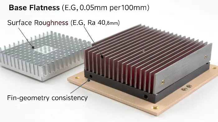
For heatsinks, base flatness (e.g., <0.05mm per 100mm), surface roughness (e.g., Ra <0.8µm), and fin geometry consistency are paramount for maximizing thermal contact and heat dissipation efficiency.

Heatsinks are all about one thing: getting heat away from sensitive electronic components as efficiently as possible. I’ve worked on numerous projects where thermal management was the primary design challenge. The interface between the heat-generating component, like a CPU or a high-power LED, and the base of the heatsink is the most critical area. If this interface isn’t perfect, the heatsink can’t do its job properly. - Base Flatness: The surface of the heatsink that makes contact with the electronic component must be exceptionally flat. Any gaps, bows, or warping, even if they are microscopic, will trap air. Air is a terrible conductor of heat. These air gaps act as insulators, significantly reducing the heatsink’s ability to draw heat away. We often specify flatness within 0.05mm per 100mm of surface length, and sometimes even tighter for very high-power applications.
- Surface Roughness (Ra): A smoother surface allows for better intimate contact between the heatsink and the component, especially when a thermal interface material (TIM), like thermal paste, is used. A lower Ra value (e.g., below 0.8 micrometers, sometimes even down to 0.4 micrometers) means fewer microscopic peaks and valleys, allowing the TIM to spread evenly and fill all voids.
-
Fin Spacing and Thickness: The consistency of the heatsink fins – their spacing, thickness, and height – directly impacts airflow and the total surface area available for heat to dissipate into the surrounding air through convection. Deviations in fin geometry can lead to unexpected hotspots or a general reduction in cooling capacity.
Consider these key aspects for heatsink tolerances:Heatsink Feature Critical Tolerance Type Impact on Performance Desired Value Example Base Contact Area Flatness Reduces thermal resistance, ensures uniform contact pressure <0.05mm over 100mm length Base Contact Area Surface Roughness (Ra) Optimizes TIM spread, minimizes air gaps at micro-level Ra < 0.8 µm (often <0.4 µm) Fin Geometry Thickness, Spacing, Ht. Ensures consistent airflow, predictable cooling performance ±0.1mm on critical dimensions Mounting Features Position, Parallelism Correct pressure on CPU/component, secure and stable fit ±0.05mm to ±0.1mm Poor tolerances in these areas mean the heatsink simply won’t perform as expected. This can lead to component overheating, reduced operational lifespan, and even system failure.
How Do Material Choices Impact Tolerances in Electronic Components?
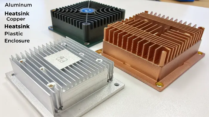
Choosing between aluminum or copper for your heatsink? Does a plastic versus metal enclosure affect the achievable precision? Material properties significantly influence machining tolerances.
Softer materials like aluminum machine easily to tight tolerances. Harder metals or many plastics may require different cutting strategies. Thermal expansion also varies, impacting final part dimensions.

The material you select for an electronics enclosure or a heatsink directly impacts the tolerances we can achieve and, importantly, maintain throughout the part’s life. This is a conversation I always have early in the design process with clients like Alex, who need to balance performance with manufacturing reality. - Machinability:
- Aluminum (e.g., 6061, 6063): This is a workhorse material. It offers excellent machinability. We can achieve very tight tolerances relatively easily and cost-effectively with aluminum. It’s a common choice for both enclosures and heatsinks due to its good thermal conductivity and strength-to-weight ratio.
- Copper (e.g., C101, C110): Copper has superior thermal conductivity compared to aluminum, making it ideal for high-performance heatsinks. However, it’s softer and can be "gummy" to machine. Achieving very fine features or extremely smooth surface finishes (low Ra values) can be more challenging and may require specialized tooling or techniques, but high precision is definitely still possible.
- Plastics (e.g., ABS, Polycarbonate, Nylon): Generally, plastics are easier to machine than metals in terms of cutting forces. However, they have significantly higher coefficients of thermal expansion. This means temperature control during the machining process and considering the operating temperature of the final application is much more critical to maintain dimensional stability and tolerances. They also may not hold as sharp an edge or offer the same rigidity as metals.
- Thermal Expansion (CTE): All materials expand when heated and contract when cooled. This is a crucial factor for parts that will experience temperature fluctuations, which is almost always the case for heatsinks and many outdoor or industrial enclosures. The Coefficient of Thermal Expansion (CTE) must be considered during design. A part machined to precise dimensions at a workshop temperature of 20°C might be out of tolerance if it operates at 60°C or -10°C.
-
Stress Relief and Stability: Some materials, particularly certain plastics or metal parts that have undergone heavy machining, can warp or change dimension after machining due to the release of internal stresses. Sometimes, an annealing or stress-relieving heat treatment step is needed before final machining to ensure dimensional stability.
Here’s a quick comparison table:Material General Machinability Thermal Stability (Low CTE) Common Use in Electronics Key Tolerance Considerations Aluminum (e.g., 6061) Excellent Good Enclosures, Heatsinks Holds tight tolerances well; good all-rounder. Copper (e.g., C110) Good Good High-Perf. Heatsinks Softer, requires care for fine finishes/features; burr control. ABS Plastic Good Moderate (Higher CTE) Enclosures, Prototypes Higher CTE; potential for warping if not managed; less rigid. Polycarbonate (PC) Fair to Good Moderate (Higher CTE) Rugged Enclosures Tougher than ABS; can be more prone to stress cracking if not machined carefully. Understanding these material characteristics helps us at QuickCNCs select the right machining parameters, cutting tools, and advise clients on realistic tolerance expectations and potential design adjustments.
Can DFM Optimize Tolerances and Costs for Enclosures and Heatsinks?
Are high precision demands driving up your component costs? Could your design be simplified without sacrificing essential function? DFM helps balance precision with affordability.
Yes, Design for Manufacturability (DFM) reviews can identify overly tight or unnecessary tolerances, suggesting alternatives that reduce machining time, complexity, and cost while ensuring full performance.

Design for Manufacturability (DFM) is a critical process I emphasize heavily at QuickCNCs. It’s all about making smart design choices upfront to ensure parts can be manufactured efficiently, accurately, and economically, without compromising their intended function. For electronics enclosures and heatsinks, where tolerances can be demanding, DFM can be a real game-changer for managing both precision and costs. - Tolerance Analysis: We meticulously review every specified tolerance. Is a requirement for ±0.01mm truly necessary for a particular feature, or would ±0.05mm or even ±0.1mm suffice without impacting form, fit, or function? This is a common discussion point. Over-tolerancing – specifying tighter tolerances than functionally required – is one of the biggest drivers of unnecessary cost in machined parts.
- Feature Simplification: Complex shapes, very deep pockets, or extremely thin walls can be challenging and expensive to machine accurately. During a DFM review, we ask: Can a feature be simplified? For example, instead of a very thin wall that might deflect during machining, could it be made slightly thicker to improve rigidity and ease of machining without adverse effects?
- Standard Tooling and Practices: Designing features that can be created with standard cutting tools, rather than requiring custom-ground tools, saves significant time and money. This often relates to things like internal corner radii (using a radius instead of a sharp corner allows a standard end mill to be used), hole depths relative to diameters, and thread specifications.
-
Material Selection Re-evaluation: Sometimes, a slightly different alloy of aluminum or a different grade of plastic might offer better machinability for the required tolerances, or it might be more stable, potentially at a lower material cost or with reduced machining cycle times.
Consider this DFM thought process when designing:DFM Aspect Question for Enclosures/Heatsinks Potential Benefit from Optimization Tolerance Stack-up How do individual part tolerances accumulate in the final assembly? Loosen non-critical tolerances, focus only on critical interfaces. Feature Accessibility Can all features be easily and directly reached by cutting tools? Reduced number of setups, faster machining times, lower fixturing costs. Surface Finish Needs Is a very fine (expensive) surface finish needed on non-contact or non-visible surfaces? Save on secondary operations like polishing or special machining passes. Radii vs. Sharp Corners Are internal sharp corners functionally essential? Could radii be used? Allows use of standard end mills, faster machining, stronger corners. I recall a project involving an intricate heatsink design for a medical device. The initial design had many extremely tight tolerances. Through a collaborative DFM process, we identified several areas where tolerances could be strategically relaxed slightly without impacting thermal performance or assembly. This simple review significantly reduced machining time and the overall cost for the client, making the project more viable. It’s always about finding that optimal sweet spot between perfect design intent and practical, cost-effective manufacturing.
Conclusion
Precise tolerances for electronics enclosures and heatsinks are vital. They ensure correct fit, effective sealing, optimal thermal performance, and long-term reliability for sensitive electronic systems.
