Struggling with automotive parts that don’t fit or function right? Are unclear tolerance needs causing rejections and delays? Meeting demanding auto standards requires precision.
Meeting automotive machining standards involves understanding specific ISO norms like ISO 2768, applying appropriate general tolerances, and adhering to stricter, part-specific callouts dictated by function and material for optimal performance.
Automotive components are critical. They need to fit perfectly and work reliably for many miles. At QuickCNCs, we often help engineers and procurement teams, much like Alex working on his precision robotics, get automotive parts machined to exact specifications. The tolerances in the automotive industry can be very tight. It’s not just about making a part; it’s about making it right every single time. Let’s explore what it takes to meet these industry standards, drawing from my experience in global manufacturing.
What is the ISO Standard for Machining Tolerances in Automotive Applications?
Confused about which ISO standard applies to your automotive parts? Are general tolerance notes causing uncertainty in production? A common standard exists, but specifics are key.
ISO 2768 is a widely referenced standard for general machining tolerances (linear, angular, and geometrical – classes f, m, c, v and H, K, L). However, automotive often demands tighter, explicitly stated tolerances.
When we talk about general tolerances in machining, ISO 2768 often comes up. This standard has different classes. For linear and angular dimensions, you have ‘f’ for fine, ‘m’ for medium, ‘c’ for coarse, and ‘v’ for very coarse. For geometrical tolerances like flatness, straightness, and perpendicularity, you have classes H, K, and L. So, a drawing might say "ISO 2768-mK". This tells the machinist to apply medium general tolerances for dimensions and class K for geometric features unless a specific tolerance is noted elsewhere.
In the automotive world, while ISO 2768 provides a good baseline for non-critical features, many components require much tighter control. Think about an engine part or a transmission component. The tolerances there are usually specified directly on the drawing, overriding any general tolerance notes. I’ve seen this with clients like Alex; his robotic arm components also need specific, tight tolerances beyond general standards. The material of the part and its exact function will always dictate the necessary precision.
What are Considered Standard Tolerances for Automotive Machining?
Wondering what’s "normal" for automotive tolerances? Are you unsure if your drawing callouts are typical or overly strict? "Standard" varies greatly by application.
Standard automotive tolerances can range from ±0.1mm to ±0.5mm for general features. Critical parts like engine or transmission components often demand much tighter precision, frequently ±0.01mm to ±0.025mm or better.
Defining a single "standard" tolerance for all automotive machining is tricky because the range is so wide. It really depends on the part’s function. For example, a simple bracket holding a piece of trim might be perfectly fine with a tolerance of ±0.5mm. But, if you look at internal engine components, like pistons and cylinders, or parts of the transmission, the tolerances shrink dramatically. Here, we often see requirements of ±0.01mm, ±0.02mm, or even tighter. My insight includes an example where an engine cylinder block needs a flatness tolerance of 0.02mm. This is critical to ensure a good seal with the cylinder head and prevent leaks.
At QuickCNCs, when we review drawings for automotive parts, we pay close attention to these specific callouts. We also consider the material. A plastic interior part will have different "standard" tolerances than a hardened steel gear. Understanding these nuances is key to providing accurate quotes and delivering parts that meet the high expectations of the automotive industry.
What is a Reasonable Tolerance for Machining Automotive Parts?
Struggling to decide on tolerances for your automotive design? Are you over-tolerancing, increasing costs, or under-tolerancing, risking failure? Finding the balance is crucial.
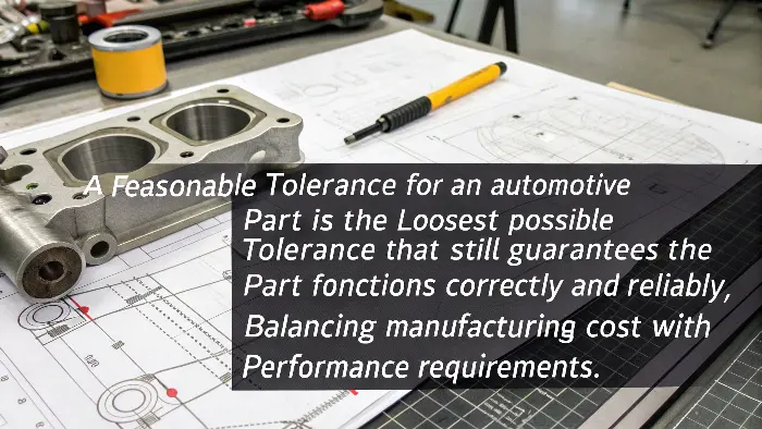
A reasonable tolerance for an automotive part is the loosest possible tolerance that still guarantees the part functions correctly and reliably, balancing manufacturing cost with performance requirements.

The golden rule I always share with clients, including engineers like Alex, is "as loose as possible, as tight as necessary." This is especially true in the automotive sector. Why? Because unnecessarily tight tolerances drive up costs significantly. They mean more machining time, potentially more specialized tooling, higher inspection demands, and often a higher scrap rate. If a part can function perfectly well with a tolerance of ±0.1mm, there’s no need to specify ±0.01mm. That extra zero can add a lot to the price tag.
However, for critical functions, "tight as necessary" is paramount. For example, the bearing surface on a crankshaft needs to be incredibly precise. Here, a tight tolerance isn’t just reasonable; it’s essential for the engine’s longevity and performance. So, "reasonable" is a balance. It involves understanding the part’s role in the assembly, its interaction with other components, and the manufacturing processes involved. This is where Design for Manufacturability (DFM) discussions become very valuable. We often work with clients to review tolerances and ensure they are practical and cost-effective without compromising function.
How Does ISO 2768 mK Apply to Automotive Components?
Heard of ISO 2768 mK but unsure how it fits automotive? Does this general tolerance cover all your needs? It’s a useful baseline, but often not enough.
ISO 2768-mK specifies medium general tolerances for linear/angular dimensions (‘m’) and general geometrical tolerances (‘K’). It’s suitable as a default for non-critical features on many automotive parts.

Let’s break down ISO 2768-mK. The ‘m’ refers to the "medium" class for linear and angular dimensions. This means there’s a table in the standard that says, for a dimension of a certain size, what the permissible deviation is. The ‘K’ refers to a class for general geometrical tolerances – things like flatness, straightness, perpendicularity, and symmetry. Again, there are defined values based on the nominal size or length of the feature.
In an automotive context, you might find "ISO 2768-mK" in the general notes of a drawing. This is a good way to cover less critical features without cluttering the drawing with too many specific tolerances. For instance, the overall dimensions of a simple cover or a mounting bracket might fall under this. However, for critical interfaces, mating surfaces, bearing bores, or features affecting alignment – like for gears, where an angular tolerance for alignment might be ±0.5° (as per my insights), this general tolerance is usually overridden by a specific, tighter tolerance shown directly on that feature. So, ISO 2768-mK is a helpful starting point, but for the high-performance demands of most automotive systems, specific, carefully calculated tolerances are the norm.
Conclusion
Meeting automotive tolerances demands understanding standards like ISO 2768, applying reasonable limits, and focusing on critical feature precision. This ensures functionality and reliability in demanding applications.
