Designing parts for CNC machining can be tricky. You want precision, but complex designs often lead to sky-high costs and delays. It’s frustrating when your innovative designs get bogged down by manufacturing issues or unexpected expenses, right? But what if a few simple DfM (Design for Manufacturability) tweaks could change all that?
Yes, by following key DfM principles, you can significantly reduce CNC machining costs, shorten lead times, and improve part quality. These 8 tips will help you optimize your designs for efficient production, ensuring your components are made right, on time, and within budget. I’ve seen these work wonders for many clients.
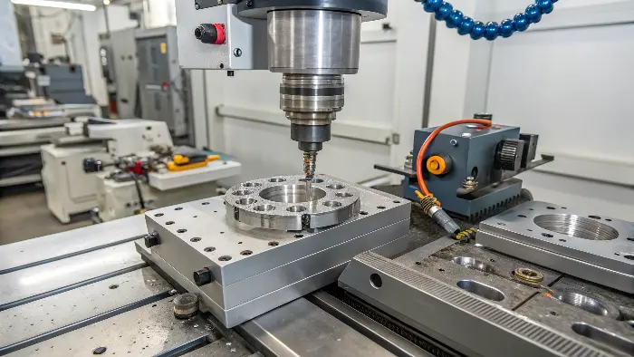
I’ve been in the CNC machining world for over a decade, first on the shop floor and now helping engineers like Alex from Germany get their parts made efficiently. I’ve seen firsthand how small design changes can make a huge difference. So, let’s dive into these tips that can transform your CNC machining experience. You’ll want to stick around for these.
How Can Proper Wall Thickness and Cavity Design Save Your CNC Machining Budget?
Problem: Thin walls break easily during machining, and deep, narrow cavities are tough for tools to reach. Agitation: This means more machine time, special tooling, and a higher chance of scrapped parts – all eating into your budget. Solution: But by designing optimal wall thicknesses and accessible cavities, you can avoid these headaches.
Maintaining wall thickness above 0.02 inches (0.5mm) for metals and 0.04 inches (1mm) for plastics, and avoiding deep cavities with sharp internal corners, drastically cuts machining time and risk. This simple foresight prevents tool breakage, reduces vibration, and ensures part integrity, saving you money.
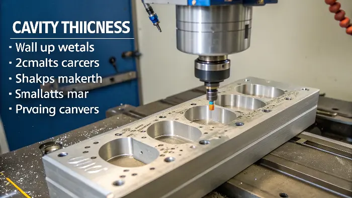
When I work with clients like Alex, who designs high-tolerance robotic parts, wall thickness is a common discussion point. He once sent a design for an aluminum housing with walls just 0.3mm thick in some areas. The problem? Standard end mills can easily deflect or break such thin walls, especially in metals. We had to use specialized, smaller tools and much slower cutting speeds, which increased the cost.
- Minimum Wall Thickness (Tip 1):
- Metals: Generally, aim for at least 0.02 inches (0.5mm). For robust parts, 0.03 inches (0.8mm) or more is better.
- Plastics: Plastics are less rigid, so aim for 0.04 inches (1mm) minimum, ideally 0.06 inches (1.5mm).
- Deep Cavities & Sharp Corners (Tip 2):
- Deep, narrow cavities are challenging because standard tools might not reach the bottom, or chip evacuation becomes a problem. This often requires longer, thinner tools that are prone to vibration and breakage.
- Sharp internal corners are impossible to machine with a round cutting tool. The tool will always leave a radius. If a sharp corner is absolutely needed, it might require secondary operations like EDM, adding significant cost. It’s better to design internal corners with a radius slightly larger than the cutting tool’s radius. For example, if a 1/4" end mill is used, an internal radius of 0.130" or greater is ideal.
Here’s a quick comparison:
| Feature | Problematic Design | Recommended Design | Benefit |
|---|---|---|---|
| Wall Thickness (Al) | < 0.5mm | > 0.8mm | Reduced vibration, fewer scrapped parts |
| Internal Corners | Sharp (0mm radius) | Radius > Tool Radius (e.g., >3mm) | Machinable with standard tools, faster |
| Cavity Depth/Width | Depth > 6x Width | Depth < 4x Width | Better tool access, chip evacuation |
By addressing these early in the design, Alex was able to revise his housing, making it much more manufacturable and cost-effective without compromising its function.
Are You Over-Designing Grooves and Aesthetic Features on Your CNC Parts?
Problem: Intricate grooves and purely cosmetic features look great on screen but can be a nightmare to machine. Agitation: These complexities often require special tooling, multiple setups, and significantly longer machining times, inflating your costs unnecessarily. Solution: Simplifying these elements can lead to big savings without sacrificing core functionality.
Yes, limiting groove depth to 4-6 times the groove’s corner radius and avoiding non-functional complex aesthetic features can dramatically reduce machining costs. Simpler designs mean faster production, less specialized tooling, and a more straightforward manufacturing process, directly benefiting your bottom line.
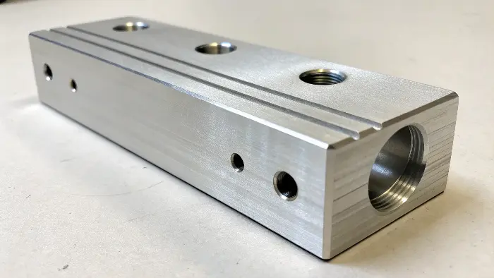
I remember a project for a client developing consumer electronics. They had designed a beautiful, intricate wave pattern on the aluminum casing. While it looked stunning, machining those tiny, flowing grooves was incredibly time-consuming. Each groove needed a very small ball-end mill and many passes.
- Groove Depth and Radius (Tip 3):
- The rule of thumb is to limit the depth of a groove or slot to no more than 4-6 times its width or, if it has internal radii, 4-6 times the smallest corner radius. Deeper grooves require longer, more fragile tools, increasing the risk of tool breakage and chatter.
- For example, if you have a groove with a 1mm corner radius, try to keep its depth below 4mm to 6mm.
- Complex Aesthetic Features (Tip 4):
- While aesthetics are important, especially for consumer products, every complex curve, tiny engraving, or non-functional sculpted surface adds machining time. Ask yourself: "Is this feature essential for the part’s function or market appeal, or can it be simplified?"
- Sometimes, a slight modification, like changing a complex 3D contour to a simpler 2.5D feature, can cut machining time significantly. For instance, instead of a fully sculpted surface, perhaps a series of straight cuts or a simpler curve would suffice.
Consider the impact:
| Feature Detail | Over-Designed Example | DfM-Optimized Example | Impact on Machining |
|---|---|---|---|
| Groove Depth | 10x corner radius | < 6x corner radius | Reduced tool wear, faster cutting |
| Aesthetic Surface | Complex 3D organic shape | Simpler 2.5D profile, flat faces | Fewer tool paths, less machine time |
| Small Text/Logos | Deep, intricate engraving | Shallow engraving, larger font | Faster engraving, less risk of defects |
We worked with the electronics client to simplify the wave pattern, making it slightly shallower and using larger radii. The visual impact was still great, but the machining time, and therefore cost, dropped by nearly 30%. It’s always a balance, but functionality and manufacturability should often lead.
Could Simpler Edges and Looser Tolerances Make Your CNC Parts Cheaper and Faster?
Problem: Specifying fillets on all edges and demanding ultra-tight tolerances everywhere seems like good engineering practice. Agitation: But this often leads to unnecessary machining steps, specialized inspections, and higher rejection rates, slowing down production and increasing costs. Solution: Using chamfers where possible and applying tight tolerances only where critical can streamline manufacturing.
Absolutely. Using chamfers instead of fillets for edge breaks, where functionally appropriate, and avoiding non-critical tolerances tighter than +/- 0.005 inches (+/- 0.127mm) can significantly reduce machining time and cost. These choices simplify toolpaths and reduce the need for meticulous, time-consuming operations.
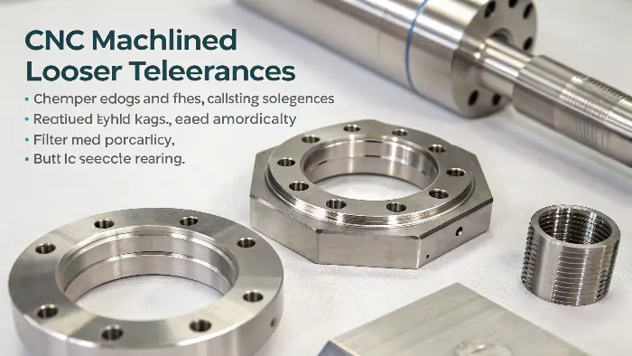
Alex, my engineer client from Germany, often deals with parts requiring high precision. However, in his early designs, he used to apply a default tight tolerance block to the entire drawing. We discussed how this impacts cost.
- Chamfers vs. Fillets (Radiused Edges) (Tip 5):
- Fillets (rounded edges) often require a ball-end mill and contouring toolpaths, which can be slower than using a standard square end mill or a chamfer tool.
- Chamfers (angled edges) can often be created with the same tool used for face milling or with a simple chamfering tool in a single pass. They are generally quicker and cheaper to machine.
- When to use which? If an edge needs to be deburred or slightly protected, a chamfer is usually sufficient and more cost-effective. Fillets are better if a specific radius is needed for stress distribution, sealing, or a smooth transition for mating parts. I always ask, "Is this radius critical, or is it just for breaking the edge?"
- Tolerances (Tip 6):
- Tighter tolerances mean more careful machining, slower feed rates, potentially more finishing passes, and more rigorous (and expensive) inspection.
- The standard machining tolerance for many shops is around +/- 0.005 inches (+/- 0.127mm). Anything tighter should be justified by functional requirements.
- Critical vs. Non-Critical: Identify which features truly need high precision (e.g., bearing fits, mating surfaces) and apply tight tolerances only there. For non-critical features, looser tolerances are perfectly acceptable and much cheaper.
Here’s how these choices play out:
| Aspect | Over-Specified Approach | DfM Optimized Approach | Benefit |
|---|---|---|---|
| Edge Treatment | Fillets on all external edges | Chamfers on most edges, fillets if critical | Faster machining, less tool wear |
| General Tolerance | +/- 0.001" on all dimensions | +/- 0.005" general, tight where needed | Reduced machining time, lower inspection cost |
| Surface Finish | Very fine finish everywhere | Standard finish, fine only if required | Fewer finishing passes, faster cycle time |
By reviewing his drawings and relaxing tolerances on non-critical dimensions, Alex was able to reduce the cost of his prototypes without affecting their performance in the robotic assemblies. It’s about being precise where it matters, not everywhere.
Are Your Hole Designs and Material Choices Optimized for CNC Machining?
Problem: Designing custom hole sizes or choosing hard-to-machine materials can seem like a minor detail. Agitation: But these choices can lead to needing special drill bits, longer machining times, increased tool wear, and ultimately, higher costs for your parts. Solution: Standardizing holes and selecting machinable materials can significantly streamline production.
Yes, using standard drill sizes, keeping tapped hole depths reasonable, and selecting materials with good machinability ratings are key DfM practices. These considerations reduce the need for custom tooling, minimize machining time, and lower overall part cost, making your production smoother and more economical.
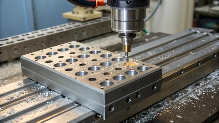
I often see designs come through with very specific, non-standard hole diameters or unnecessarily deep tapped holes. While we can machine almost anything, these small details add up.
- Standardize Hole Sizes and Tap Depths (Tip 7):
- Standard Drill Sizes: Designing holes that can be made with standard drill bit sizes is always cheaper and faster. Custom sizes require reaming or boring, adding operations. Check a standard drill chart when designing.
- Tapped Holes:
- Depth: For most applications, a tapped thread depth of 1.5 to 2 times the bolt diameter is sufficient. Going deeper (e.g., 3x diameter) doesn’t significantly increase holding strength but makes tapping much harder, increasing tap wear and breakage risk, especially in blind holes.
- Clearance: Ensure there’s enough clearance at the bottom of a blind tapped hole for the tap to pass through and for chips to accumulate (typically an extra 0.1 to 0.2 inches or 2-5mm beyond the required thread depth).
- Consider Material Choice Carefully for Machinability (Tip 8):
- Machinability Rating: Different materials machine very differently. Materials like Aluminum 6061, Brass, or free-machining steels are easy to cut, allowing for faster speeds and feeds, and result in lower tool wear.
- Harder Materials: Stainless steels (like 316 or 17-4 PH), titanium, or superalloys are much tougher to machine. They require slower speeds, specialized tooling, and more robust machine setups, all of which increase cost.
- Trade-offs: Always weigh the material’s properties (strength, corrosion resistance, weight) against its machinability and cost. Sometimes, a slightly less "ideal" but more machinable material can meet functional requirements at a significantly lower price. For example, if moderate corrosion resistance is needed, could Aluminum 6061 with anodizing work instead of Stainless Steel 304?
Let’s look at the impact:
| DfM Aspect | Less Optimal Choice | Recommended DfM Choice | Benefit |
|---|---|---|---|
| Hole Diameter | Custom size (e.g., 6.13mm) | Standard drill size (e.g., 6.0mm or 6.2mm) | No need for reaming, faster |
| Tapped Hole Depth | 3x bolt diameter in a blind hole | 1.5x bolt diameter + clearance | Less tap wear/breakage, faster tapping |
| Material Choice | Exotic alloy when not strictly needed | Standard, machinable alloy (e.g., Al 6061) | Lower material cost, faster machining, less tool wear |
I once had a client who specified a high-strength titanium alloy for a bracket that saw minimal stress. After discussion, we found that a good grade of aluminum would be more than sufficient and cut the part cost by nearly 60%. It’s about smart choices from the start.
Conclusion
These 8 DfM tips—wall thickness, cavities, grooves, aesthetics, chamfers, tolerances, standard holes, and material choice—are your allies. Implementing them will make your CNC machined parts more cost-effective, faster to produce, and consistently higher quality. Start applying them today!
