Getting precision machined parts made can be a real challenge. You need tight tolerances and complex geometries, but often face high costs and long lead times. It’s frustrating when your carefully designed components hit manufacturing roadblocks, isn’t it? But what if a few smart design choices could change all that?
Yes, by applying key Design for Manufacturability (DFM) tips, you can significantly reduce costs, shorten delivery times, and improve the quality of your precision machined parts. These 7 tips are essential for any engineer looking to optimize their designs for efficient and successful production. I’ve seen them work wonders for many clients.
I’m Jerry Zou, founder of QuickCNCs. With over a decade in CNC machining, from the shop floor to global sourcing, I’ve helped engineers like Alex in Germany navigate the complexities of precision manufacturing. These DFM tips are born from real-world experience. Let’s dive in and see how they can help you.
Are Sharp Internal Corners Sabotaging Your Precision Machining Costs?
Problem: Your design includes sharp, 90-degree internal corners, which look clean on your CAD model. Agitation: However, these are often impossible or very expensive to create with standard CNC milling tools, leading to increased costs and potential delays. Solution: Designing internal corners with appropriate radii can make a huge difference.
Yes, avoiding sharp internal corners and instead designing them with radii (ideally larger than the cutting tool’s radius) significantly reduces machining time and cost. Standard end mills are round, so they naturally create a radius. Forcing a sharp corner often requires slower, specialized processes like EDM.
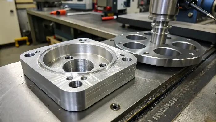
I remember Alex, an engineer I work with, once designed a complex housing with several internal pockets that had perfectly square corners. While it looked neat, the machine shop flagged it immediately. Standard milling tools simply can’t get into a sharp internal corner.
-
Why Sharp Corners are Problematic:
- A rotating cutting tool (like an end mill) has a diameter. When it cuts an internal pocket, the smallest radius it can create is its own radius.
- To get a "sharper" corner, a smaller diameter tool is needed, which is less rigid, slower, and more prone to breaking.
- Achieving a truly sharp corner often requires Electrical Discharge Machining (EDM), a much slower and more expensive secondary operation.
-
The DFM Solution: Add Radii
- Always add a radius to internal vertical corners.
- A good rule of thumb: make the radius at least 1/8" (3mm), or even better, slightly larger than the radius of the end mill likely to be used for that feature. For deeper pockets, a larger radius is even more beneficial as it allows for a more rigid tool.
- If a specific, small radius is needed, ensure it’s clearly called out.
Here’s a simple comparison:
| Feature | Problematic Design | DFM Recommended Design | Impact |
|---|---|---|---|
| Internal Corner | 0mm Radius (Sharp) | Radius > 1mm (e.g., 3mm) | Faster machining, standard tooling, lower cost |
| Tool Choice | Requires very small tool or EDM | Standard end mill can be used | Reduced tool wear, no secondary operations |
By adding generous radii to his design, Alex avoided the need for EDM and cut the machining cost for that housing by nearly 20%. It’s a simple change with a big impact.
How Can Optimizing Wall Thickness Prevent Issues in Precision Machining?
Problem: Your design features very thin walls to save weight or space. Agitation: These thin sections can vibrate excessively during machining, leading to poor surface finish, inaccuracies, or even part failure on the machine. Solution: Designing with adequate and uniform wall thickness is crucial.
Yes, designing parts with sufficient and consistent wall thickness (generally above 0.030" or 0.8mm for metals, and 0.060" or 1.5mm for plastics) prevents warping, reduces vibration, and ensures structural integrity during the machining process. This leads to better quality parts and fewer failures.
Thin walls are a common challenge in precision machining. I once worked on a project for an aerospace component where the initial design had walls as thin as 0.5mm in some areas. The machinist struggled with chatter and maintaining tolerance.
-
Why Thin Walls are Risky:
- Vibration (Chatter): Thin walls lack rigidity and can vibrate when the cutting tool engages, leading to an uneven surface finish and dimensional inaccuracies.
- Warping: The forces and heat generated during machining can cause thin sections to warp or distort.
- Breakage: Extremely thin walls might simply break under cutting pressure.
- Fixturing Difficulties: Holding thin-walled parts securely without deforming them can be challenging.
-
DFM Guidelines for Wall Thickness:
- Minimums: For metals like aluminum, aim for at least 0.030" (0.8mm). For plastics, which are less rigid, aim for 0.060" (1.5mm). These are general guidelines; specific applications might allow for thinner walls if carefully managed.
- Uniformity: Try to keep wall thickness as uniform as possible. Abrupt changes from thick to thin sections can cause stress concentrations and warping.
- Ribs & Gussets: If thin walls are unavoidable for functional reasons, consider adding ribs or gussets to provide support and increase stiffness.
Consider these points:
| Wall Characteristic | Problematic Approach | DFM Recommended Approach | Benefit |
|---|---|---|---|
| Thickness (Metal) | < 0.5mm | > 0.8mm, ideally > 1mm | Reduced vibration, better dimensional stability |
| Thickness (Plastic) | < 1.0mm | > 1.5mm | Less warping, improved strength |
| Transitions | Sharp thick-to-thin changes | Gradual transitions, fillets | Reduced stress, more uniform cooling/heating |
| Support | Unsupported thin sections | Add ribs or supporting features | Increased rigidity, easier machining |
By slightly increasing the wall thickness and adding small stiffening ribs to the aerospace component, we solved the chatter problem and achieved the required precision.
Could Relaxing Non-Critical Tolerances Unlock Savings on Your Precision Parts?
Problem: You’ve applied very tight tolerances to every dimension on your drawing, believing it ensures quality. Agitation: This often leads to significantly higher machining costs, longer lead times, and increased scrap rates, as achieving ultra-tight tolerances is difficult and time-consuming. Solution: Apply tight tolerances only where they are functionally critical.
Absolutely. By relaxing tolerances on non-critical features to standard machining capabilities (e.g., +/- 0.005" or +/- 0.127mm), you can drastically reduce manufacturing costs and lead times. Reserve tight tolerances only for dimensions that directly impact the part’s fit, form, or function.
Alex, the German engineer I often work with, designs parts for robotic systems where precision is key. However, in his early days, he used to put a very tight general tolerance on all his drawings. We had a discussion about how this impacts cost.
-
The Cost of Tight Tolerances:
- Slower Machining: Requires slower speeds, finer cuts, and potentially more passes.
- Special Tooling/Processes: May necessitate specialized tools, grinding, or lapping.
- Increased Inspection: More time and sophisticated equipment are needed for verification.
- Higher Scrap Rate: The tighter the tolerance, the higher the chance a part will be out of spec.
-
DFM Approach to Tolerancing:
- Identify Critical Dimensions: Determine which features truly need high precision for the part to function correctly (e.g., bearing bores, mating surfaces, alignment pins).
- Use Standard Tolerances Elsewhere: For non-critical features, use the shop’s standard tolerance or a general tolerance like +/- 0.005" (+/- 0.127mm).
- Communicate Clearly: Use clear callouts on your drawings. Specify a general tolerance and then highlight the critical dimensions with their tighter tolerances. GD&T (Geometric Dimensioning and Tolerancing) is invaluable here.
Here’s how tolerance choices impact production:
| Tolerance Level | Typical Range (+/- inch) | Impact on Machining | DFM Strategy |
|---|---|---|---|
| Standard | +/- 0.005" to +/- 0.010" | Standard speeds, feeds, and inspection methods. | Apply to all non-critical features. |
| Tight | +/- 0.001" to +/- 0.002" | Slower machining, more careful setups, more inspection. | Use only for critical fits and functions. |
| Very Tight | < +/- 0.0005" | Specialized processes (grinding, lapping), CMM inspection. | Avoid unless absolutely essential; explore alternatives. |
By reviewing his designs and relaxing tolerances on non-functional surfaces, Alex often reduces part costs by 10-30% without any impact on performance. It’s about being smart with precision.
Is Your Material Choice Truly Optimized for Precision Machining Success?
Problem: You’ve selected a material based purely on its ideal physical properties, without much thought to its machinability. Agitation: This can lead to difficult and slow machining, rapid tool wear, and high material costs, even if the material itself isn’t exotic. Solution: Strategically choose materials that balance performance with good machinability.
Yes, selecting materials with good machinability ratings, while still meeting functional requirements, is crucial for cost-effective precision machining. Materials like Aluminum 6061, Brass, or certain plastics machine much faster and with less tool wear than harder materials like stainless steels or titanium.
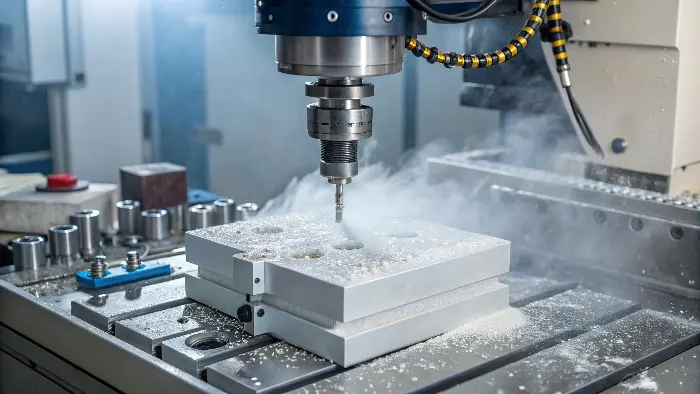
Material selection is a big factor. I once had a client specify a high-grade, work-hardening stainless steel for a bracket that saw relatively low stress. The machinists struggled, and tool costs were high.
-
What is Machinability?
Machinability refers to the ease with which a material can be cut, drilled, milled, etc., while maintaining good tool life and surface finish. It’s often expressed as a rating relative to a standard material (like AISI 1212 steel). -
Factors to Consider:
- Functional Requirements: Strength, hardness, corrosion resistance, weight, temperature resistance, etc. These are paramount.
- Machinability Rating: How easily does it cut?
- Material Cost: Raw material prices vary significantly.
- Tool Wear: Harder, more abrasive materials wear out cutting tools faster, increasing tooling costs.
- Cycle Time: Easier-to-machine materials allow for faster speeds and feeds.
-
DFM Strategy for Materials:
- Always start with the functional needs.
- Then, among the materials that meet those needs, consider their machinability and cost.
- Don’t over-specify. If a standard aluminum alloy will do the job, don’t choose an exotic titanium alloy unless absolutely necessary.
- Consult with your machinist or a materials expert if unsure.
Here’s a look at some common materials:
| Material Group | Examples | General Machinability | Considerations |
|---|---|---|---|
| Aluminum Alloys | 6061, 7075, MIC-6 | Excellent to Good | Lightweight, good strength-to-weight, cost-effective. |
| Steels (Carbon) | 1018, 1045 | Good to Fair | Strong, versatile, cost-effective. |
| Steels (Stainless) | 303, 304, 316, 17-4 PH | Fair to Difficult | Corrosion-resistant, strong; 303 is more machinable. |
| Plastics | Delrin (Acetal), Nylon, PEEK | Excellent to Fair | Lightweight, insulating; some are abrasive. |
| Titanium Alloys | Grade 2, Grade 5 (Ti-6Al-4V) | Difficult | High strength-to-weight, corrosion-resistant, expensive. |
For the bracket I mentioned, we switched to a more machinable grade of stainless steel (303 instead of 316 initially considered for a less critical application) and saved considerable machining time and tooling costs.
Why Does Simplifying Complex Features Drastically Improve Precision Machinability?
Problem: Your design includes highly intricate shapes, very small features, or deep, narrow pockets. Agitation: These complexities often require specialized tooling, multiple machine setups, very slow cutting speeds, and significantly increase the risk of errors or tool breakage. Solution: Simplify features wherever possible without compromising function.
Simplifying part geometry by reducing the number of complex features, using standard shapes, and avoiding unnecessarily deep or narrow cavities makes parts significantly easier and cheaper to machine. Simpler designs mean faster programming, quicker setups, and more efficient material removal.
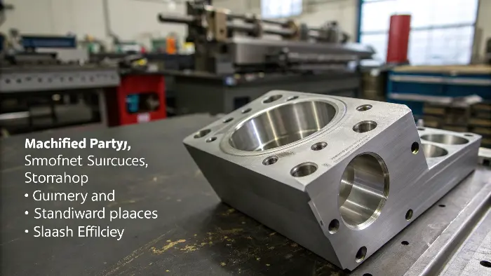
"Keep it simple" is a mantra in DFM. I often see engineers, in their quest for innovation, design parts that are more complex than they need to be. Alex once showed me a design for a sensor mount with many small, sculpted surfaces.
-
What Makes a Feature "Complex" for CNC?
- Deep, Narrow Pockets/Slots: Difficult for tools to reach, poor chip evacuation, risk of tool deflection or breakage. Ratio of depth to width is key.
- Very Small Features: Require tiny, fragile tools and slow machining.
- Complex 3D Contours/Surfaces: Require ball-end mills and many small step-overs, leading to long machining times.
- Numerous Unique Features: Each different feature might require a different tool or setup.
- Features on Multiple Faces: Can require re-fixturing the part, adding setup time and potential for error.
-
DFM Strategies for Simplification:
- Question Every Feature: Is this curve, slot, or hole absolutely necessary for the part’s function?
- Standardize: Use standard hole sizes, common radii, and consistent feature designs.
- Combine Features: Can two separate features be combined into one simpler one?
- Reduce Setups: Try to design features so they can be machined from the fewest possible orientations (ideally one or two).
- 2.5D vs. 3D: If a 2.5D feature (profiles and pockets with vertical walls) can achieve the function, it’s usually much cheaper than a full 3D contoured surface.
Consider the impact of simplification:
| Feature Aspect | Complex Approach | Simplified DFM Approach | Benefit |
|---|---|---|---|
| Pockets | Very deep and narrow | Wider, shallower, or through-pockets | Better tool access, faster material removal |
| Surfaces | Intricate 3D sculpted surfaces | Flat surfaces, simple curves (2.5D) | Less programming, faster machining |
| Small Details | Tiny engravings, very small radii | Larger, more robust details | Easier to machine, less risk of tool breakage |
| Number of Setups | Features on all 6 sides | Features consolidated to 1-2 sides | Reduced setup time, improved accuracy |
For Alex’s sensor mount, we identified that some of the sculpted surfaces were purely aesthetic and could be simplified to flat angled faces, cutting machining time by almost half.
Are You Considering Feature Depth Limitations in Your Precision Machined Designs?
Problem: Your design includes very deep pockets or long, small-diameter holes. Agitation: Machining deep features is challenging due to tool reach, rigidity, chip evacuation, and coolant delivery, leading to slower speeds, increased tool wear, and potential inaccuracies. Solution: Design features with depth-to-diameter/width ratios in mind.
Yes, paying close attention to the depth of features like pockets, slots, and holes is critical. Generally, try to limit the depth of a pocket or slot to 4-6 times its width, and hole depth to 6-10 times its diameter, especially for smaller diameters, to ensure efficient and accurate machining.
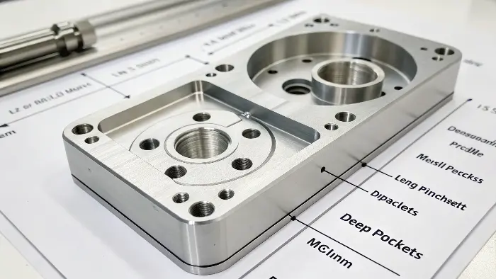
Feature depth is a common DFM checkpoint. When a tool has to reach deep into a part, several problems arise. I’ve seen projects delayed because a critical hole was just too deep for standard tooling to drill accurately.
-
Challenges with Deep Features:
- Tool Rigidity: Longer tools are less rigid and more prone to deflection (bending) and vibration, leading to inaccuracies and poor surface finish.
- Chip Evacuation: Chips can get packed in deep holes or pockets, causing tool breakage or re-cutting of chips, which damages the surface.
- Coolant Delivery: Getting coolant to the cutting edge in a deep feature can be difficult.
- Cycle Time: Machining deep features often requires multiple pecking cycles (for drilling) or slower feed rates and shallower step-downs (for milling).
-
DFM Guidelines for Feature Depth:
- Pockets/Slots: Aim for a depth-to-width ratio of no more than 4:1. If deeper is needed, make the pocket wider if possible.
- Holes: For standard drills, a depth-to-diameter ratio of 6:1 to 10:1 is a reasonable limit. Deeper holes may require specialized gundrills or pecking cycles.
- Internal Radii in Deep Pockets: Ensure corner radii are large enough to accommodate a suitably rigid tool for the full depth.
- Through-Features: If possible, design pockets or holes to go all the way through the part, as this helps with chip evacuation.
Here’s how depth impacts machining:
| Feature Type | Problematic Depth Example | DFM Recommended Depth/Ratio | Benefit |
|---|---|---|---|
| Depth = 10x Width | Depth < 4x Width | Better tool stability, faster material removal | |
| Blind Hole | Depth = 15x Diameter (small dia) | Depth < 8x Diameter, or use pecking | Reduced tool breakage, better chip evacuation |
| Tapped Hole | Thread depth > 3x Diameter | Thread depth ~1.5x Diameter | Less tap wear, stronger threads (often) |
If a deep feature is unavoidable, discuss it with your machinist early. They might suggest design tweaks or specific tooling strategies.
How Does Providing Comprehensive Information Streamline Your Precision Machining Project?
Problem: Your drawings or CAD files are missing key details, or your requirements are ambiguous. Agitation: This leads to back-and-forth questions, assumptions by the machinist (which can be wrong), delays in quoting, and potentially parts that don’t meet your expectations. Solution: Provide clear, complete, and unambiguous information upfront.
Providing comprehensive information, including fully dimensioned drawings, 3D CAD models, material specifications, critical tolerances, surface finish requirements, and quantities, is vital. Clear communication eliminates guesswork, speeds up quoting and production, and ensures you get the parts you need.
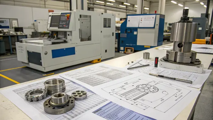
This might seem obvious, but it’s a DFM tip that’s often overlooked. As a sourcing professional, the quality of information I receive directly impacts how quickly and accurately I can get quotes and parts for my clients.
-
Essential Information to Provide:
- 3D CAD Model: In a standard format like STEP, IGES, or Parasolid. This is the primary source for CAM programming.
- 2D Drawings: Fully dimensioned, clearly indicating all features, critical tolerances (using GD&T where appropriate), surface finish requirements, material type and temper, and any special instructions (e.g., deburring, specific edge breaks, inspection criteria).
- Quantity and Lead Time: How many parts do you need, and what is your desired delivery schedule?
- Critical Features: Highlight any features that are absolutely critical to the part’s function.
- Post-Processing: Specify any required heat treatment, plating, anodizing, painting, or assembly.
-
Why It Matters for DFM:
- Accurate Quoting: Complete information allows for precise cost estimation.
- Correct Manufacturing: Reduces the chance of errors or misinterpretations.
- Efficient Planning: Helps the machinist plan the optimal manufacturing process.
- Faster Turnaround: Minimizes delays caused by missing information.
Consider the difference clear information makes:
| Information Aspect | Vague/Missing Information | Clear/Comprehensive Information | Outcome |
|---|---|---|---|
| Tolerances | "Tight tolerances needed" | Specific tolerances on critical dimensions, general on others. | Accurate machining, cost control. |
| Material | "Aluminum" | "Aluminum 6061-T6" | Correct material used, predictable machining. |
| Surface Finish | Not specified | Ra values called out on specific surfaces. | Part meets aesthetic/functional surface requirements. |
| Critical Features | Not highlighted | Key features clearly marked or noted. | Machinist focuses attention where it’s most needed. |
I always tell Alex, "The more information you give me, the better and faster I can help you." A well-documented design is a cornerstone of successful precision machining.
Conclusion
These 7 DFM tips—managing internal corners, wall thickness, tolerances, material choice, design simplicity, feature depth, and clear communication—are your roadmap. Implementing them will make your precision machining projects smoother, more cost-effective, and ultimately more successful. Start applying them today!
